
Automatic welding device for medical protective clothing

A technology of protective clothing and automatic welding, applied in the field of medical protective clothing, can solve the problems of difficulty in realizing ultrasonic automatic welding, and achieve the effect of efficient and convenient use and flexible and flexible use.

Active Publication Date: 2021-01-01
湖北新鑫无纺布有限公司
View PDF11 Cites 0 Cited by
  • Summary
  • Abstract
  • Description
  • Claims
  • Application Information

AI Technical Summary

Problems solved by technology

However, due to the fact that the existing medical protective clothing is generally thick and has a breathable membrane, there are still certain difficulties in the realization of ultrasonic automatic welding

Method used


Image

  • Automatic welding device for medical protective clothing
  • Automatic welding device for medical protective clothing
  • Automatic welding device for medical protective clothing

Examples


example 1

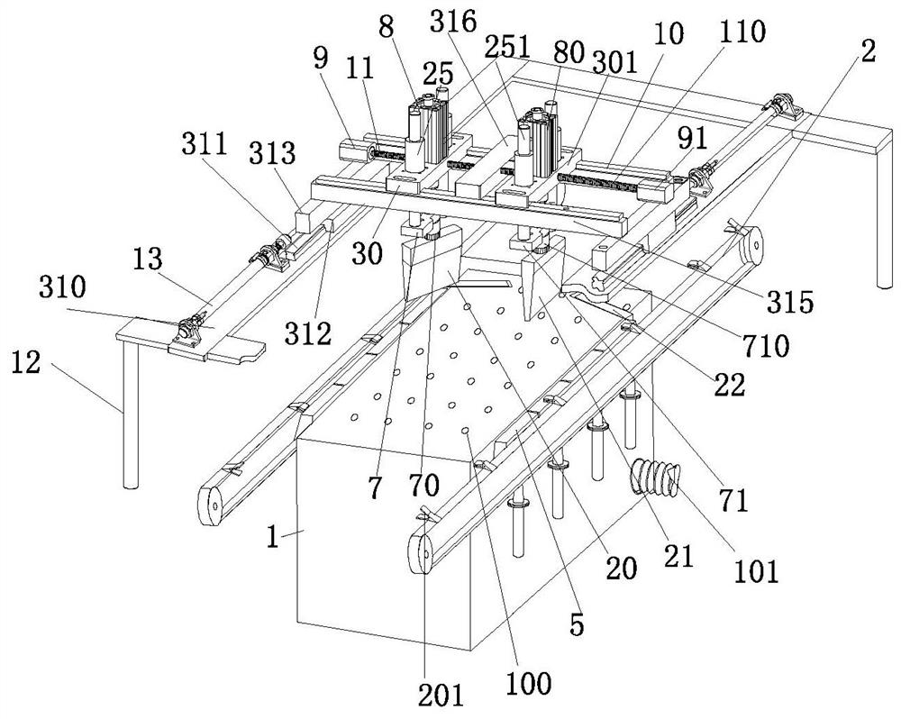
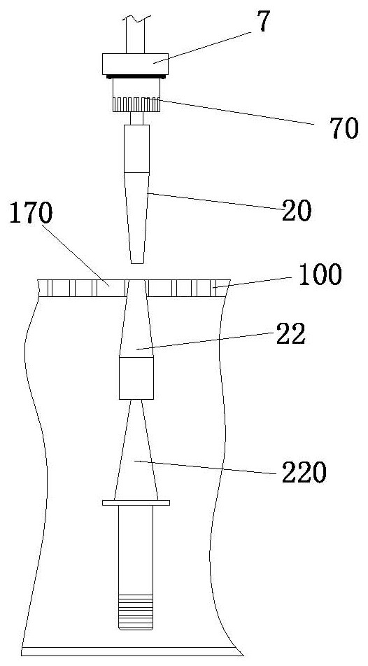
[0027] Example 1: Reference Figure 1-4 , an automatic welding device for medical protective clothing, including a cabinet-type workbench 1, and the two sides of the cabinet-type workbench 1 are respectively provided with side-mounted ultrasonic die heads 5, and the ultrasonic die head is connected to the top of the ultrasonic vibrator 220.

[0028] A conveyor belt 2 is provided on the outside of the side-mounted ultrasonic die head 5, and an electromagnetic clip 201 is provided on the conveyor belt 2. Supports 12 are provided on both sides of the cabinet-type workbench 1, and a top plate 310 is provided on the top of the support 12. , and a more stable structure is: the top of the bracket 12 is connected to the top plate 310 through the gantry frame 321 .

[0029] A guide rail 311 is fixed on the top plate 310, and a slider 312 is arranged on the guide rail 311. One end of the slider 312 is connected with the telescopic mechanism 13 on the top. The telescopic mechanism is one...

example 2

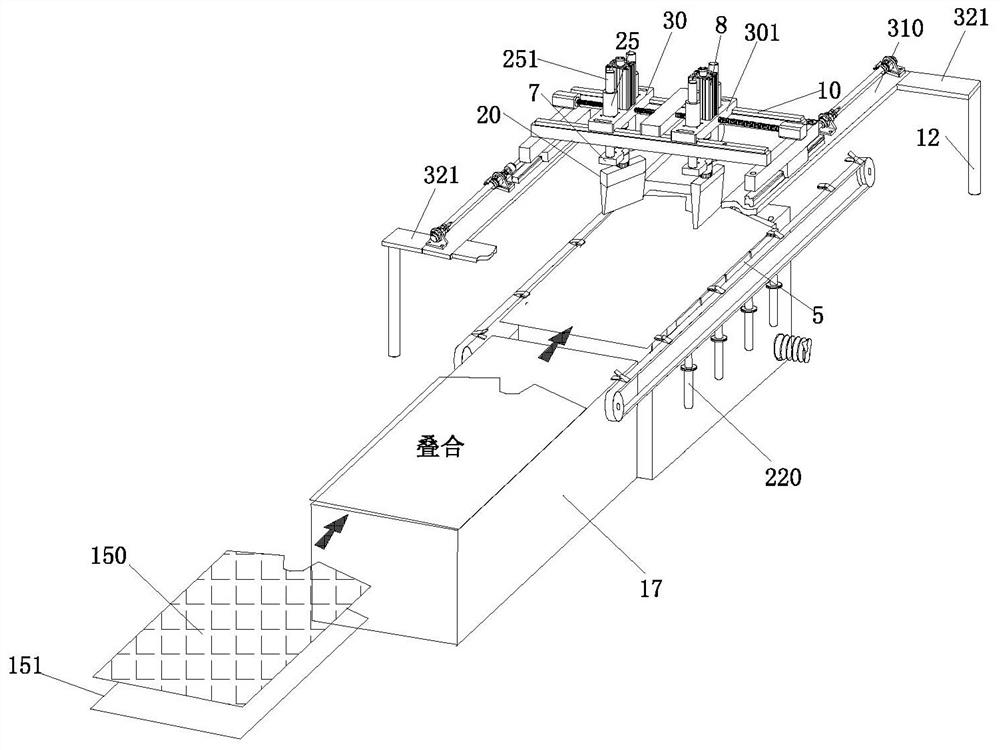
[0037] Example 2: Reference Figure 1-4 , on the basis of example 1, the cabinet type workbench 1 front part is connected with the stacking workbench 17, and the upper cutting piece 150 of the protective clothing body and the lower cutting piece 151 of the protective clothing body are placed on the folding workbench 17. The conveyor belt 2 is extended to the front end of the stacking workbench 17, and the non-woven fabric is cut into the upper cutting piece 150 of the protective clothing body and the lower cutting piece 151 of the protective clothing body, after being stacked on the folding workbench 17, open When the electromagnetic clip 201 passes through the stacking workbench 17, the clip is closed, and the upper part 150 of the protective clothing body and the lower part 151 of the protective clothing body are clamped as a whole to be transported forward, and then passed through the working panel of the cabinet type workbench 1. At the same time, the panel 170 is provided...


PUM


Abstract

The invention provides an automatic welding device for medical protective clothing. The automatic welding device comprises a cabinet type workbench and is characterized in that side ultrasonic die heads are arranged on the two sides of the cabinet type workbench correspondingly, wherein a conveying belt is arranged on the outer sides of the side ultrasonic die heads; electromagnetic clamps are arranged on the conveying belt; supports are arranged on the two sides of the cabinet type workbench; a top plate is arranged at the top ends of the supports; a guide rail is fixed to the top plate; a sliding block is arranged on the guide rail; one end of the sliding block is connected with a top telescopic mechanism; and the top of the sliding block is fixedly connected with the bottom of a longitudinal beam. According to the automatic welding device, ultrasonic die pressing automatic welding is adopted, and use is efficient and convenient. The welding positions of an upper protective clothingbody cut piece and a lower protective clothing body cut piece are subjected to automatic pressure welding through a first telescopic mechanism and a second telescopic mechanism, and thorough fusion ofspecial cloth for the protective clothing is achieved.

Description

technical field [0001] The invention relates to the field of medical protective clothing, in particular to an automatic welding device for medical protective clothing. Background technique [0002] Medical protective clothing has a strong role in isolating germs, harmful ultrafine dust, acidic solutions, and salt solutions, and keeping the environment clean. Medical protective clothing is generally made of PP (polypropylene, accounting for 62% of the total) non-woven fabric and a special breathable film, which has strong air permeability, anti-static, and better impermeability. While resisting a variety of organic solvents, acid and alkali corrosion, it has high impact resistance. [0003] At present, in the production of medical protective clothing, most of the existing technologies use manual sewing. In addition to the defects of low efficiency, the sewing machine sewing will also produce a large number of needle holes, which greatly affects the sealing performance of pro...

Claims


Application Information

Patent Timeline
Patent Type & Authority Applications(China)
IPC IPC(8): B29C65/08B29C65/78B29C65/80A41H43/04
CPCB29C65/08B29C65/7847B29C65/7858B29C65/80B29C66/022B29C66/41B29C66/822A41H43/04
Inventor 潘元静王帅敏
Owner 湖北新鑫无纺布有限公司
Learn More