
Magnet group for a solenoid valve

A magnet assembly, solenoid valve technology, applied in the direction of electromagnets, electrical components, electromagnetic terminals/connectors, etc., can solve the problems of inability to achieve, difficult to manufacture, and difficult to design the connection position, and achieve a large degree of freedom and simple adaptation. Effect

Active Publication Date: 2013-03-13
ROBERT BOSCH GMBH
View PDF1 Cites 0 Cited by
  • Summary
  • Abstract
  • Description
  • Claims
  • Application Information

AI Technical Summary

Problems solved by technology

[0003] The fuel injection valve known from EP 1612400 A1 has the following disadvantages: It is rather laborious to manufacture
In addition, there is the disadvantage that the design of the connection points for the fuel return path is complex and an adaptation to different applications cannot be realized or can only be realized with great effort.

Method used


Image

  • Magnet group for a solenoid valve
  • Magnet group for a solenoid valve
  • Magnet group for a solenoid valve

Examples


Embodiment Construction

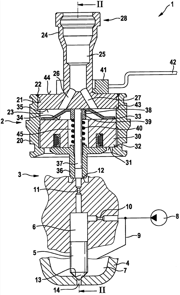
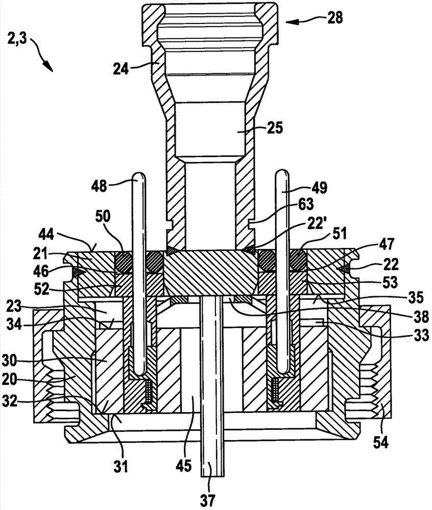
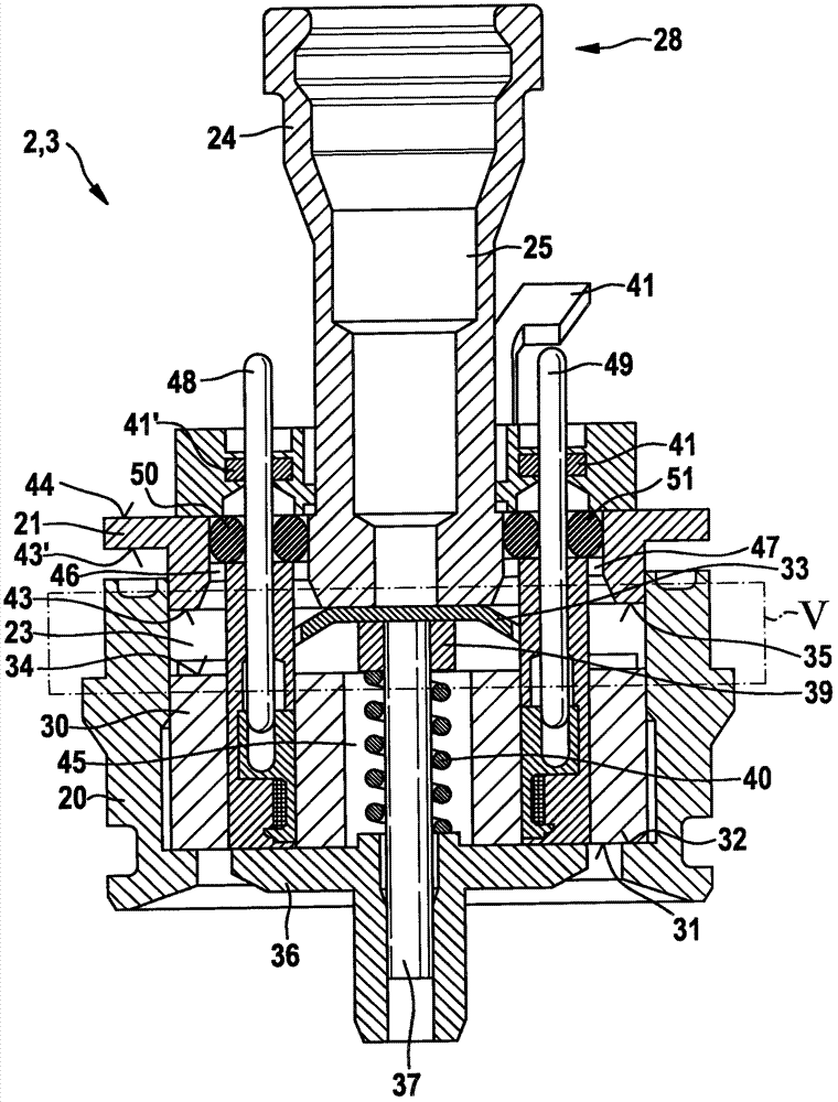
[0025] figure 1 A fuel injector 1 with a magnet arrangement (magnet component set) 2 according to a first exemplary embodiment of the invention is shown in a simplified, schematic sectional illustration. The fuel injection valve 1 can be used in particular as an injector of a fuel injection system for an air-compressed, self-igniting internal combustion engine. The fuel injection valve 1 is preferably used in a fuel injection system having a common rail which guides diesel fuel under high pressure to a plurality of fuel injection valves 1 . The magnet arrangement 2 according to the invention is particularly suitable for such fuel injection valves 1 . In this case, the magnet assembly 2 can be used as part of a solenoid valve 3 , which serves as a solenoid actuator for the fuel injection valve 1 for actuating the fuel injection valve 1 . However, the fuel injector 1 according to the invention and the magnet arrangement 2 according to the invention are also suitable for other ...


PUM


Abstract

A magnet group (2) serves in particular for a magnet actuator (3) of a fuel injection valve (1). The magnet group (2) has a housing part (20) into which a coil (30) is placed. In addition, an armature (36) is arranged on a first side (31) of the coil (30). Furthermore, a cover (21), which closes off the housing part (20), is arranged on a second side (34), facing away from the first side (31), of the coil (30), wherein the cover (21) is connected to the housing part (20) by a weld seam (22). The multi-part design permits, in particular, adaptation of an interface (28) to a connector (24) which is connected to the housing part (20) or embodied in one piece therewith.

Description

technical field [0001] The invention relates to a magnet assembly for a solenoid valve, in particular a magnet assembly for an electromagnetic actuator of a fuel injection valve. The invention relates in particular to the field of injectors for fuel injection devices of air-compressed, self-igniting internal combustion engines. Background technique [0002] A fuel injection valve for an internal combustion engine is known from EP 1612400 A1. The known fuel injection valve has an electromagnetic actuator which controls the fuel flow through the discharge throttle. The fuel injection valve can thus be indirectly actuated to inject fuel. The magnet assembly of the electromagnetic actuator is arranged in mutually screwed housing parts. Here, a plastic material is provided which surrounds important elements of the magnet assembly. The electrical insulation from the metal housing of the fuel injection valve is ensured by the plastic material. Furthermore, the sealing rings ar...

Claims


Application Information

Patent Timeline
Patent Type & Authority Patents(China)
IPC IPC(8): H01F7/126
CPCH01F7/1638F02M47/027F02M63/0031F02M63/0033F02M55/002H01F2007/062H01F7/126F02M2200/8084F02M63/0078F02M63/0017
Inventor F·豪伊A·博尔曼D·克劳克C·布切尔
Owner ROBERT BOSCH GMBH
Learn More