
Buoyancy water lifting equipment for water conservancy and hydropower

A technology of water conservancy, hydropower and buoyancy, which is applied in the direction of mechanical equipment, hydroelectric power generation, cleaning methods using tools, etc., can solve problems affecting water lifting efficiency, sliding wall corrosion, scale formation, etc., and achieve the effect of avoiding internal water backflow

Inactive Publication Date: 2021-01-01
王东鑫
View PDF0 Cites 0 Cited by
  • Summary
  • Abstract
  • Description
  • Claims
  • Application Information

AI Technical Summary

Problems solved by technology

[0004] Aiming at the deficiencies in the prior art, the purpose of the present invention is to provide a buoyancy water lifting equipment for water conservancy and hydropower, to solve the problem that the buoyancy water lifting equipment for water conservancy and hydropower used in the prior art is used when building a lake hydropower station. More, so that the hardness of the water is greater, so that when the equipment is used, the floating objects supplied internally will be affected by the water quality, and scale will form on the sliding wall, so that the scale will adhere to the sliding wall for a long time, causing corrosion on the sliding wall and affecting the subsequent The problem of water extraction efficiency

Method used


Image

  • Buoyancy water lifting equipment for water conservancy and hydropower
  • Buoyancy water lifting equipment for water conservancy and hydropower
  • Buoyancy water lifting equipment for water conservancy and hydropower

Examples


Embodiment 1

[0026] as attached figure 1 to attach Figure 5 Shown:

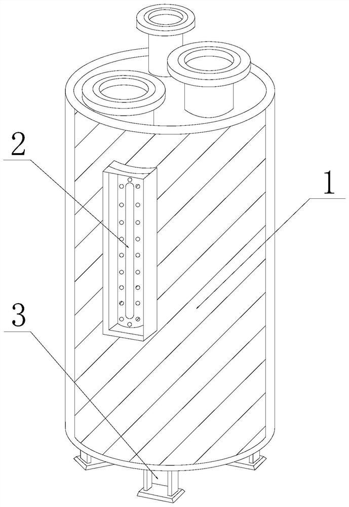
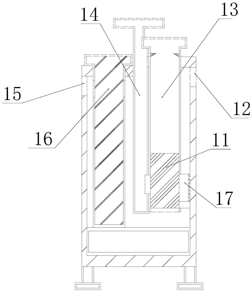
[0027] Its structure includes a container tank 1, an observation table 2, and a support base 3. The observation table 2 is nested and connected with the inside of the container tank 1, and the support base 3 is welded with the bottom end of the container tank 1. The inside of the container tank 1 includes Control valve 11, drainage hole 12, water outlet pipe 13, air pressure pipe 14, water inlet hole 15, water inlet pipe 16, air tank 17, the control valve 11 is nested and connected with the water outlet pipe 13, and the bottom of the water outlet pipe 13 is connected with the air The two walls of the groove 17 are engaged and connected, and the air pressure pipe 14 is fixed on the right side of the water inlet pipe 16 to coordinate with its activities. The wall is movably matched, and the control valve 11 is movably matched with the right wall of the air pressure pipe 14 .

[0028] Wherein, the control valve 11 includ...

Embodiment 2

[0034] as attached Figure 6 to attach Figure 7 Shown:

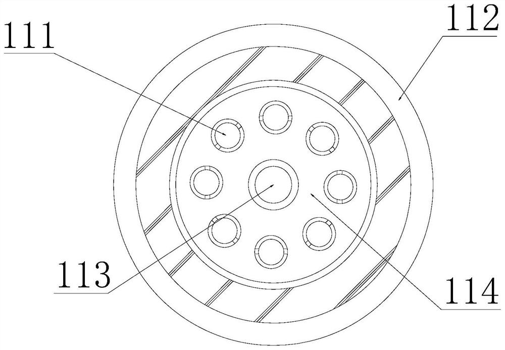
[0035]Wherein, the one-way valve 111 includes a valve piece b1, a sleeve b2, and a valve body b3, the sleeve b2 is fixed on the left and right sides of the valve body b3, and is embedded and connected with it, and the two walls of the valve piece b1 are connected with the sleeve The inside of b2 is snapped and connected, the valve piece b1 is nested inside the valve body b3, and fits with its clearance, and the sleeve b2 is provided with two, which are distributed at the left and right ends of the valve body b3 and are embedded and connected with it, wherein the valve piece b1 It is beneficial to open and close through the impact of water flow, so that the water flow can pass through its valve effectively.

[0036] Wherein, the inside of the valve body b3 includes a rotating rod b31, a spring clamp b32, a blocking plate b33, and a concave buckle b34. The inside of the buckle b34 is snapped and connected, the barrier ...


PUM


Abstract

The invention discloses buoyancy water lifting equipment for water conservancy and hydropower. The buoyancy water lifting equipment for water conservancy and hydropower structurally comprises a container tank, an observation meter and a supporting base, wherein the observation meter is connected with the interior of the container tank in a nested mode; the supporting base is connected with the bottom end of the container tank in a welded mode; a control valve, a drainage hole, a water outlet pipe, an air pressure pipe, a water inlet hole, a water inlet pipe and an air groove are arranged in the container tank; the control valve is connected with the interior of the water outlet pipe in a nested mode; the bottom of the water outlet pipe is connected with the two walls of the air groove in aclamped mode; the air pressure pipe is fixed to the right side of the water inlet pipe and is movably matched with the water inlet pipe; the drainage hole is fixed to the right side of the water outlet pipe; the water inlet hole is movably matched with the side wall of the water inlet pipe; and the control valve is movably matched with the right wall of the air pressure pipe. According to the buoyancy water lifting equipment for water conservancy and hydropower provided by the invention, water scale attached to a sliding wall is scraped back and forth by a scraper in the up-and-down floatingperiod of a scraper groove in a up-and-down floating cylinder wall through the change of water buoyancy, and the water scale is scraped off by a scraper head, so that the occurrence of the phenomenonthat the water scale is attached to the sliding wall for a long time to corrode the sliding wall is effectively avoided.

Description

technical field [0001] The invention relates to the field of water conservancy, in particular to a buoyancy water lifting device for water conservancy and hydropower. Background technique [0002] Water conservancy and hydropower is a project that rationally regulates and utilizes water energy. In the construction of existing water conservancy and hydropower projects, it pays special attention to the extraction of water energy with low energy consumption. Take the use of buoyancy of water as an example, that is, to use objects that exist in water to a certain extent. buoyancy, and when the buoyancy changes, it can effectively realize the sinking and floating of the object, so as to achieve the effect of pumping out the water; [0003] However, there are following deficiencies in the prior art: the current buoyancy water lifting equipment for water conservancy and hydropower is used when repairing lake hydroelectric power stations, because there are more impurities in the lak...

Claims


Application Information

Patent Timeline
IPC IPC(8): F04B19/00F03B17/02B08B1/00F16K15/03
CPCF04B19/00F03B17/02F16K15/03B08B1/165B08B1/30Y02E10/20
Inventor 王东鑫
Owner 王东鑫
Learn More