Hydraulic fan system and engineering machinery

A fan system, hydraulic technology, applied in the direction of fluid pressure actuation system components, mechanical equipment, machines/engines, etc., can solve the problem that the hydraulic fan system cannot automatically reverse.

Inactive Publication Date: 2021-01-01
LIUZHOU LIUGONG EXCAVATORS +2
View PDF5 Cites 1 Cited by
  • Summary
  • Abstract
  • Description
  • Claims
  • Application Information

AI Technical Summary

Problems solved by technology

[0004] The technical problem to be solved by the present invention is to provide a hydraulic fan system and construction machinery to facilitate the automatic reversing operation of the hydraulic fan in view of the problem that the existing hydraulic fan system cannot be automatically reversed or can be automatically reversed but the solution has serious defects

Method used


Image

  • Hydraulic fan system and engineering machinery
  • Hydraulic fan system and engineering machinery

Examples


Embodiment Construction

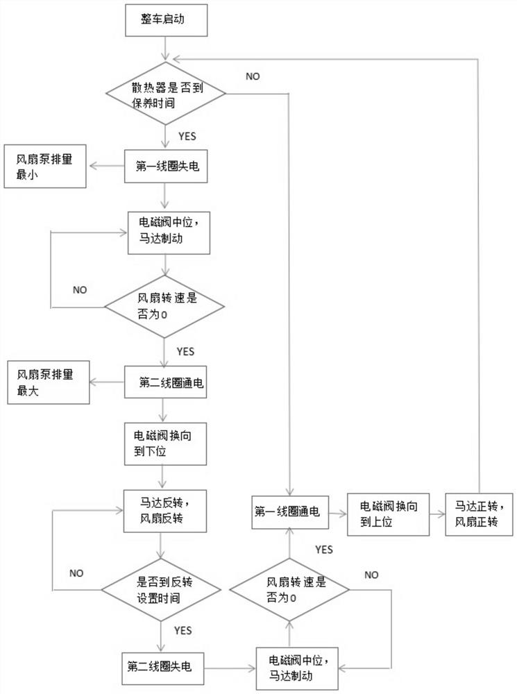
[0016]The specific implementation scheme is described below in conjunction with the drawings.

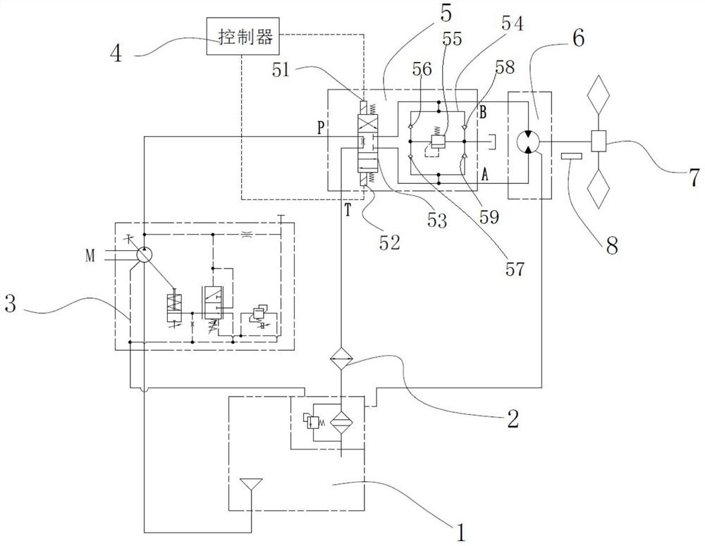
[0017]figure 1 Shows a hydraulic fan system used in construction machinery. The system is used in conjunction with the radiator of the construction machinery to drive cold air to flow through the radiator to improve the heat dissipation efficiency of the radiator. In this embodiment, the hydraulic fan system includes a hydraulic oil tank, a fan pump connected to the hydraulic oil tank at the oil inlet, a control valve, a fan motor, a controller, and a speed sensor for detecting the speed of the fan pump and connected to the controller. .

[0018]The fan pump is a variable displacement plunger pump. By controlling the displacement of the fan pump, the fan speed can be controlled.

[0019]The control valve includes an electromagnetic reversing valve 53 and a motor brake circuit 54. The electromagnetic reversing valve 53 is an M-type neutral three-position four-way reversing valve and the PT center i...


PUM


Abstract

The invention relates to a hydraulic fan system to solve the problem that the automatic reversing of an existing hydraulic fan system is not easy to operate. The invention provides a hydraulic fan system and engineering machinery. The hydraulic fan system comprises a hydraulic oil tank, a fan pump with an oil inlet end connected with the hydraulic oil tank, a control valve, a fan motor, a controller, and a rotating speed sensor which is used for detecting the rotating speed of the fan pump and is connected with the controller. The control valve comprises an M-shaped middle-position three-position four-way electromagnetic reversing valve and a motor brake loop; a port P and a port T of the electromagnetic reversing valve are connected with the fan pump and the hydraulic oil tank respectively; two working oil ports are connected with the fan motor respectively; the motor brake loop is arranged between the two working oil ports; and the electromagnetic control end of the electromagnetic reversing valve is connected with the controller. According to the hydraulic fan system and the engineering machinery provided by the invention, the electromagnetic reversing valve and the motor braking loop are arranged, motor braking stopping can be achieved during reversing, and reverse driving is conducted after stopping, so that automatic reversing is achieved, and the impact generated duringfan reversing is avoided.

Description

Technical field[0001]The invention relates to a hydraulic fan system, and more specifically, to a hydraulic fan system and engineering machinery.Background technique[0002]Hydraulic fan systems are commonly used in the field of construction machinery. The system usually includes working oil tanks, fan pumps, solenoid valves, fan motors, and fans. The fan pump is usually a variable displacement plunger pump, and the solenoid valve is usually a two-position four-way solenoid valve. In the working state, the solenoid valve coil is de-energized, the solenoid valve is in the upper position under the action of the spring, the hydraulic oil output by the fan pump flows into the fan motor A port through the solenoid valve P port, and the fan motor rotates forward to drive the fan to rotate;[0003]At present, there are two ways for the hydraulic fan system to achieve fan reversal. One can achieve automatic reversal. However, due to the performance limitation of the fan pump, the fan speed must...

Claims


Application Information

Patent Timeline
IPC IPC(8): F15B21/08F15B11/08F15B13/04F15B21/0423F04D25/04F04D25/08F04D27/00
CPCF15B21/087F15B11/08F15B13/0401F15B21/0423F04D25/04F04D25/08F04D27/00F04D27/004
Inventor 薛晗石子贡韦磊宾旭洲
Owner LIUZHOU LIUGONG EXCAVATORS
Why Eureka
Try Eureka