Underwater automatic control high-pressure valve

A technology for high-pressure valves and valve stems, which is applied in the direction of sliding valves, valve details, valve devices, etc., to achieve the effects of reducing the bending moment, avoiding harm to the environment, and wide sources of media

Inactive Publication Date: 2021-01-01
750 TEST SITE OF CHINA SHIPBUILDING IND CORP +1
View PDF5 Cites 0 Cited by
  • Summary
  • Abstract
  • Description
  • Claims
  • Application Information

AI Technical Summary

Problems solved by technology

[0006] The technical problem to be solved by the present invention is to avoid the damage of the valve stem in the underwater automatic control valve due to the bending moment, the adverse effect of the oil on the environment, and the problem of valve stem stroke observation, and to provide an underwater automatic control high pressure valve

Method used


Image

  • Underwater automatic control high-pressure valve
  • Underwater automatic control high-pressure valve
  • Underwater automatic control high-pressure valve

Examples


Embodiment Construction

[0023] The present invention will be further described below in conjunction with the accompanying drawings and embodiments.

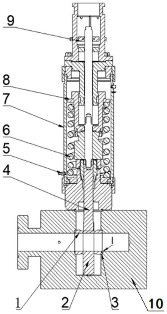
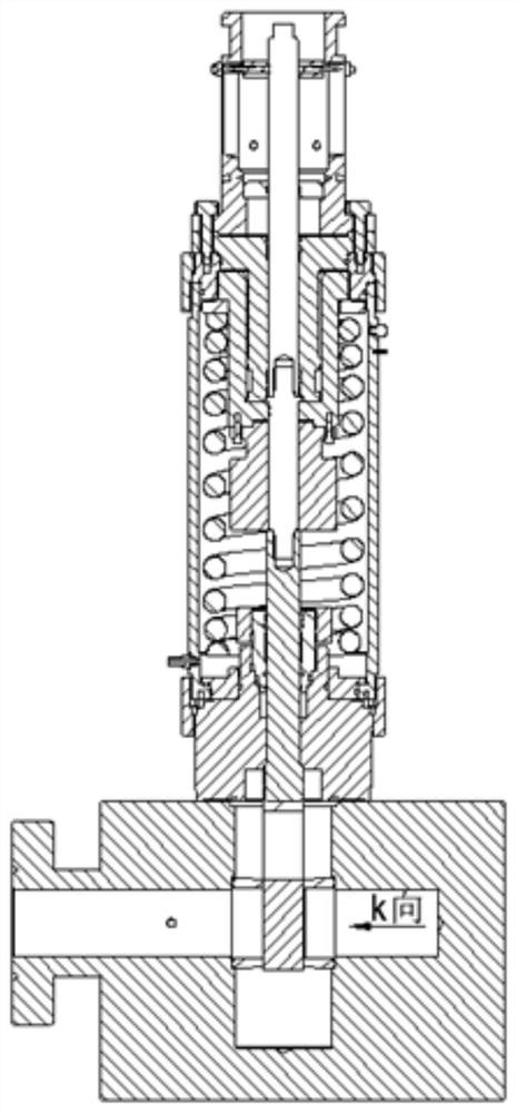
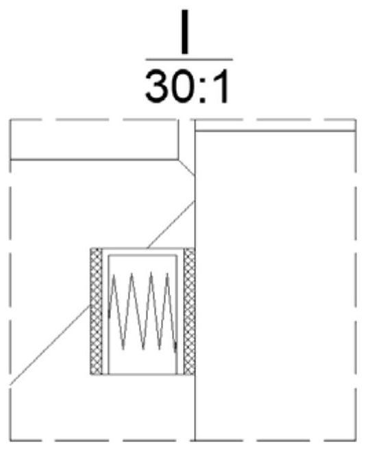
[0024] like Figure 1 to Figure 4 As shown, an underwater automatic control high-pressure valve includes a valve seat 1, a valve plate 2, a compensation sealing structure 3, a valve stem 4, a filter element 5, a spring 6, a driver 7, a piston 8, a position indicator 9, and a valve body 10 .

[0025] The valve body 10 is equipped with a valve seat 1, a valve plate 2 is arranged in the middle of the valve seat 1, the upper end of the valve plate 2 is connected to the valve stem 4, the upper end of the valve stem 4 is connected to the piston 8 in the driver 7, and the outer circumference of the piston 8 is sleeved with a reset spring 6 . The piston 8 in the driver 7 drives the valve stem 4 to drive the valve plate 2 to move up and down, so as to realize the opening and closing of the high pressure valve. The driver 7 uses seawater instead of oil as the ...


PUM


Abstract

The invention relates to an underwater automatic control high-pressure valve which comprises a valve seat, a valve plate, a valve rod, a driver and a valve body. The valve seat is installed in the valve body, the valve plate is arranged in the middle of the valve seat, the upper end of the valve plate is connected with the valve rod, and the valve plate and the valve rod are connected with each other through a T-shaped concave-convex groove structure, so that the valve plate can move left and right along the valve rod through the T-shaped concave-convex groove structure to reduce valve rod deformation caused by bending moment. The valve plate and the valve rod in the T-shaped concave-convex groove structure are respectively a T-shaped valve plate and a valve rod with a groove, or the valveplate and the valve rod are respectively a valve plate with a groove and a T-shaped valve rod. Meanwhile, a compensation seal is used for providing thrust to compensate matching between the valve plate and the valve seat; the bending moment borne by the valve rod can be reduced; and a driver adopts seawater to replace oil liquid to serve as a hydraulic driving medium, so that harm to the environment can be avoided. A position indicator is fixedly connected to the upper end of the valve rod and can move up and down in a sliding groove in the outer wall of the driver, and the stroke of the valve rod can be visually displayed.

Description

technical field [0001] The invention relates to an underwater high-pressure valve for offshore oil and gas exploitation, in particular to an automatic control high-pressure valve. Background technique [0002] The underwater automatic control valve is a very important part in the underwater production. In the traditional underwater automatic control valve, the valve stem and the valve plate are rigidly connected, and the ability to withstand bending moments is poor, and the valve stem is prone to tilt deformation after a long time. Therefore, it is necessary to use a T-shaped valve plate, which can float left and right in the concave groove of the valve stem to reduce the bending moment. [0003] At the same time, the traditional underwater automatic control valve seals only use rubber seals, which have a single function. Therefore, it is necessary to use a special sealing form (compensation seal) to provide thrust independently through the spring, so as to increase the se...

Claims


Application Information

Patent Timeline
Patent Type & Authority Applications(China)
IPC IPC(8): F16K3/02F16K3/314F16K37/00F16K31/122
CPCF16K3/0218F16K3/314F16K37/00F16K31/122
Inventor 杨帆杨勇张鹏举陈静孙现有张浩楠涂林枫
Owner 750 TEST SITE OF CHINA SHIPBUILDING IND CORP
Why Eureka
Try Eureka