Improved LED lamp

An improved technology for LED lights, applied in the field of lighting, can solve the problems of limited heat dissipation effect, slow heat conduction speed of LED lights, slow heat dissipation speed of LED lights, etc., to achieve improved heat dissipation and cooling effect, good heat dissipation effect, and improved use protection Effect

Inactive Publication Date: 2021-01-01
刘卫文
View PDF1 Cites 0 Cited by
  • Summary
  • Abstract
  • Description
  • Claims
  • Application Information

AI Technical Summary

Problems solved by technology

[0004] This improved LED lamp also has the following disadvantages in the specific operation process: the heat generated during work is conducted to the memory metal, and when it expands, the internal space of the circular table-shaped lampshade will increase, but this method is harmful to the internal space of the lampshade. The heat dissipation effect of the LED lamp is limited when it is working; at the same time, the heat conduction speed generated by the LED lamp is relatively slow, so that the heat dissipation speed of the LED lamp is relatively slow when it is working

Method used


Image

  • Improved LED lamp
  • Improved LED lamp
  • Improved LED lamp

Examples


Embodiment 1

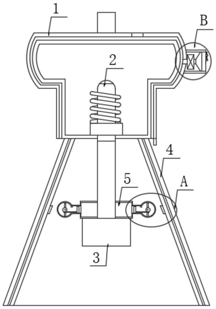
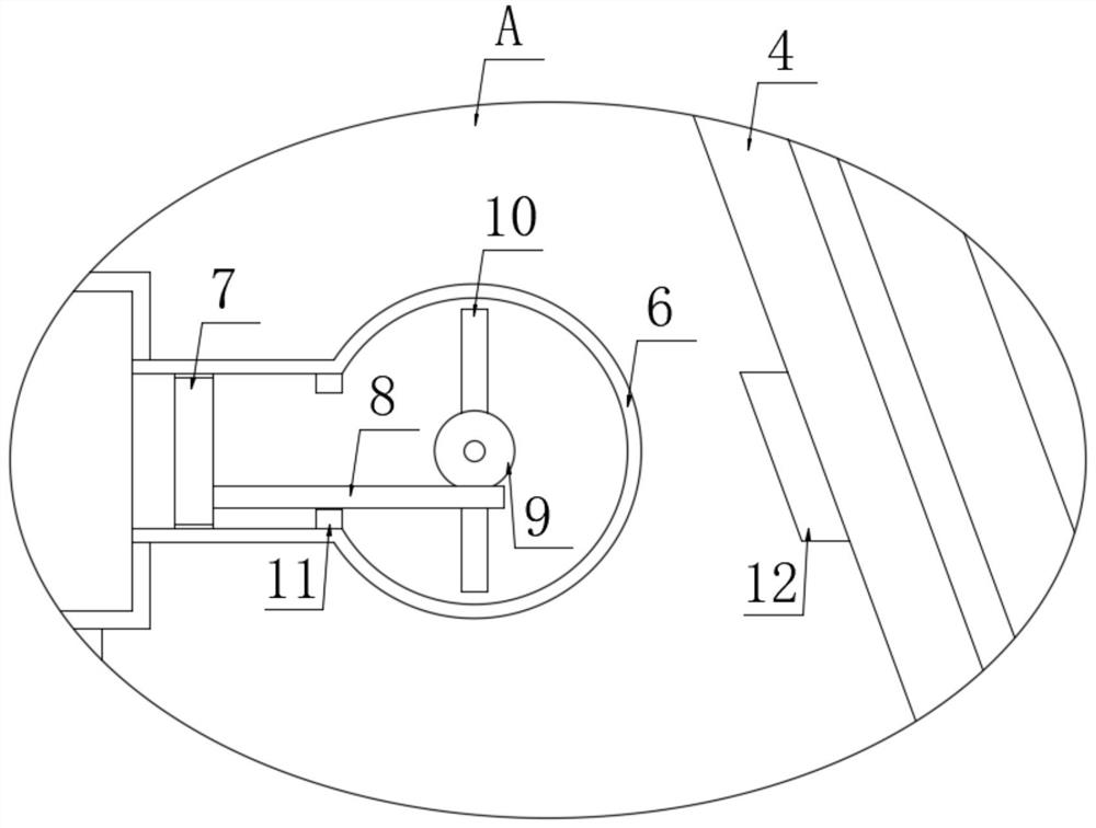
[0026] refer to Figure 1-3 , an improved LED lamp, comprising a lamp holder 1, a lamp holder 2, a lamp tube 3, two lampshades 4, a fan 13, an annular seat 5 is fixedly installed on the lamp tube 3, ammonia water is placed in the annular seat 5, and the annular seat 5 There are two mounting seats 6 fixedly connected to each other, and the mounting seats 6 are located above the ammonia water. A sealing block 7 is slidably installed in the two mounting seats 6, and a moving rod is fixedly installed at the ends of the two sealing blocks 7 that are far away from each other. 8. A gear 9 is installed in the two mounting seats 6 through the rotation of the rod body, and the gear 9 is meshed with the corresponding moving rod 8, and an unfolding structure is installed between the gear 9 and the lampshade 4;

[0027] The above points are worth noting the following:

[0028] 1. The unfolding structure is composed of two magnetic rods 10 and a magnetic block 12, a magnetic block 12 is fi...

Embodiment 2

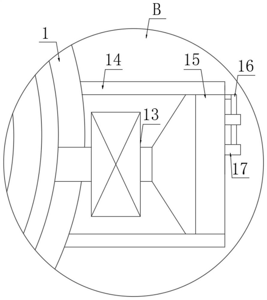
[0038] refer to Figure 4-5 The difference between this embodiment and the first embodiment is that the self-cleaning structure is composed of a mounting hole, a bearing, a rotating shaft 18, a fan blade and a scraper rod 3 19, and the filter screen 15 is provided with mounting holes for installation. The hole is equipped with a rotating shaft 18 through a bearing, and a scraping bar three 19 and a fan blade are fixedly installed on the rotating shaft 18, and the scraping bar three 19 is bonded to the outer surface of the filter screen 15.

[0039] The advantage of Embodiment 2 over Embodiment 1 is that: when the fan 13 is working, it can drive the fan blades to rotate together, and the rotation of the fan blades can drive the coaxially arranged scraper rod 3 19 to rotate, and the rotation of the scraper rod 3 19 can The filter screen 15 performs cleaning and dust removal operations, and utilizes the rotation of the fan blades to perform a preliminary cooling of the air enteri...


PUM


Abstract

The invention discloses an improved LED lamp which comprises a lamp holder, a lamp cap, a lamp tube, two lampshades and a draught fan, an annular base is fixedly installed on the lamp tube, ammonia water is placed in the annular base, two installation bases are fixedly communicated with the annular base, and the annular base and the installation bases are both made of galvanized iron sheet materials. The LED lamp has the advantages that the characteristic that heat needs to be absorbed in the decomposition process of ammonia water is utilized, heat generated in the working process of the LED lamp is absorbed to a certain degree, the heat dissipation effect can be better achieved, meanwhile, ammonia gas generated by ammonia water decomposition enables the pressure intensity in the annular base to be increased, and therefore the sealing block and the moving rod move; the moving rod moves to enable the magnetic rod to rotate, so that the magnetism between the magnetic rod and the magneticblock is changed from opposite to the same, the unfolding operation of the lampshade is realized, and the decomposition and chemical combination of ammonia gas are reversible operation, so that ammonia gas and water formed after decomposition after temperature reduction can be re-converted into ammonia water for repeated cooling and utilization.

Description

technical field [0001] The invention relates to the technical field of lighting, in particular to an improved LED lamp. Background technique [0002] When the existing LED lamps are in use, in order to avoid prolonged exposure to high temperature (above 60° is high temperature for LED lamps), heat dissipation and cooling operations will be performed on them, but the heat dissipation method of the existing LED lamps has a relatively heavy overall weight. heavy problem. [0003] The authorized invention with the patent number CN106481996B discloses a LED lamp, including a lamp body, a lamp cap, a lamp holder and a lampshade, the lamp body is connected to the lamp holder, the lamp cap is threadedly connected to the lamp holder, the lampshade is placed on the lamp body, and the lampshade includes Left half cover and right half cover, left half cover and right half cover slide socket. [0004] This improved LED lamp also has the following disadvantages in the specific operation...

Claims


Application Information

Patent Timeline
IPC IPC(8): F21K9/235F21V29/58F21V29/60F21V31/00F21V33/00F21Y115/10
CPCF21V31/00F21V31/005F21V33/00F21V29/58F21V29/60F21K9/235F21Y2115/10
Inventor 刘卫文
Owner 刘卫文
Why Eureka
Try Eureka