Wiper system installation method based on EMU wiper installation inspection device

A technology for inspection device and system installation, which is applied in vehicle cleaning, vehicle maintenance, transportation and packaging, etc., can solve problems such as the deviation of the center position of the brush arm, the jitter of the brush arm, and the inability to achieve dynamic data matching, and achieve improved installation. Process, reduce labor intensity, improve adjustment efficiency and the effect of quality data accuracy

Active Publication Date: 2022-04-29
CRRC CHANGCHUN RAILWAY VEHICLES CO LTD
View PDF12 Cites 0 Cited by
  • Summary
  • Abstract
  • Description
  • Claims
  • Application Information

AI Technical Summary

Problems solved by technology

[0003] The present invention provides a wiper system installation method based on an EMU wiper installation inspection device to solve the problem that the existing installation method is prone to the deviation of the center position of the brush arm, the vibration of the brush arm and the inability to realize the dynamic matching of data

Method used


Image

  • Wiper system installation method based on EMU wiper installation inspection device
  • Wiper system installation method based on EMU wiper installation inspection device

Examples


specific Embodiment approach 1

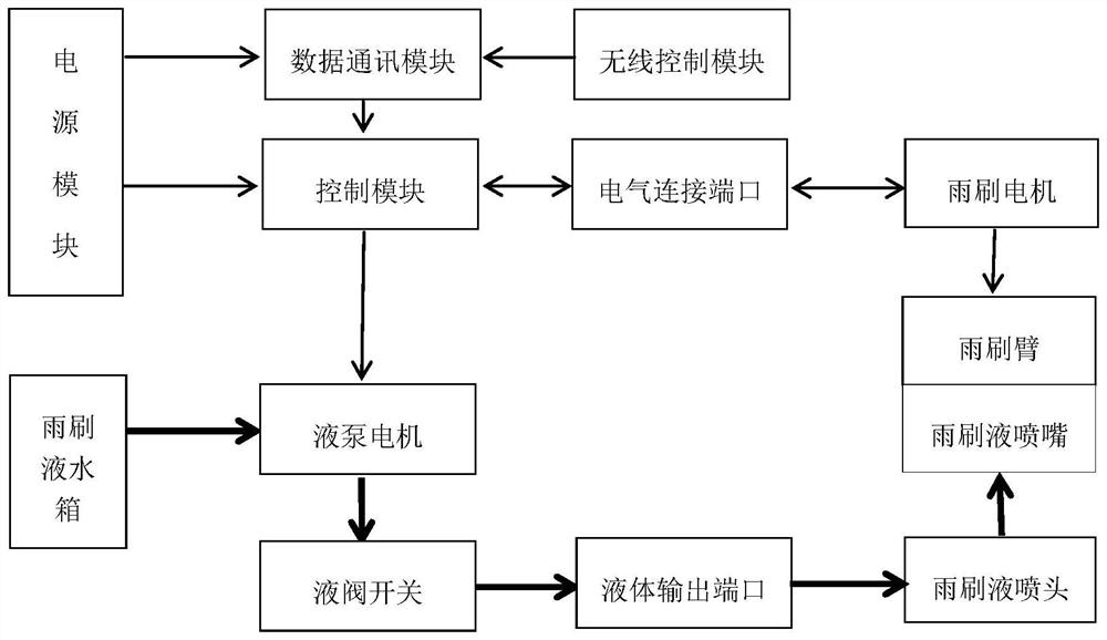
[0019] Specific implementation mode 1. Combination figure 1 Describe this embodiment, a kind of EMU wiper installation inspection device, the EMU wiper installation inspection device is composed of a power module, a control module, a data communication module, a wireless controller, an electrical connection port, a wiper fluid tank, a liquid pump motor, and a liquid valve Switches, liquid output ports, etc.; the electrical part is connected to the control module and the data communication module to provide power for the electrical part. The wireless controller sends various working condition control instructions to the control module through the data communication module. The connection port outputs power of different standards to the wiper motor and collects the feedback signal of the wiper motor to form precise control, controls the wiper motor mechanism to drive the wiper arm to complete the stroke and swing speed under different working conditions, and the control module ou...

specific Embodiment approach 2

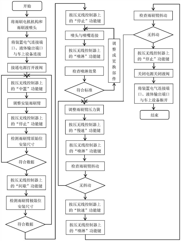
[0020] Specific embodiment two, combine figure 2 Describe this embodiment, the wiper system installation method based on EMU wiper installation inspection device, this method is realized by the following steps:

[0021] 1. Fix the wiper motor mechanism (integrated frame with wiper motor and wiper arm transmission mechanism) and the wiper fluid nozzle on the steel structure of the EMU car body, and then place the EMU wiper installation inspection device inside the EMU vehicle. The electrical connection port is connected to the wiper motor, the liquid output port is connected to the input end of the wiper fluid nozzle, the system power supply is turned on, the liquid valve switch is turned on, and the vehicle goes to the working area outside the vehicle.

[0022] 2. Press the "center" function key on the wireless controller, and the data communication module decodes and transmits the control module to control the wiper motor mechanism to run to the specified angle through the e...


PUM


Abstract

The wiper system installation method based on the EMU wiper installation inspection device relates to the technical field of EMU manufacturing, and solves the problems that the existing installation method is prone to the center position deviation of the brush arm, the vibration of the brush arm and the inability to realize the dynamic matching of data. The present invention is based on the The EMU wiper installation inspection device applies the optimized installation method of the wiper system, which can accurately adjust the installation data of all working conditions during the assembly stage, and at the same time realize all dynamic performance inspections, improve product quality, reduce labor intensity, and avoid waste of production resources. Improve the installation process, improve the adjustment efficiency and the accuracy of quality data; the installation data of the wiper system can be inspected during the installation process of the assembly site, improve the measurement means, and improve the adjustment accuracy; through the EMU wiper installation inspection device to realize all wiper Operating conditions, through dynamic functional inspection of installation quality.

Description

technical field [0001] The invention relates to the technical field of EMU manufacturing, in particular to a wiper system installation method based on an EMU wiper installation inspection device. Background technique [0002] At present, in the EMU production process, the wiper system is positioned on the basis of the distance between the lower edge of the wiper blade and the right edge of the windshield glass of the driver's cab when the wiper system is installed at the assembly site. The two connecting bolts of the arm transmission mechanism are fastened, and the pressure of the wiper arm is adjusted according to 40Nm±2. However, due to factors such as dimensional tolerances and friction coefficient differences in the windshield glass of the EMU, problems such as position deviation of the center of the brush arm and vibration of the brush arm often occur when the vehicle enters the commissioning site for functional tests. Once the above problems occur, the assemblers need...

Claims


Application Information

Patent Timeline
Patent Type & Authority Patents(China)
IPC IPC(8): G01M17/08B60S1/08
CPCG01M17/08B60S1/08
Inventor 胡俊祥刘文博李光磊邵越王士龙
Owner CRRC CHANGCHUN RAILWAY VEHICLES CO LTD
Why Eureka
Try Eureka