
Contaminated soil layer mechanical sampling device

A technology of polluted soil and sampling devices, which is applied in the direction of sampling devices, etc., can solve the problems of manual sampling such as high work intensity, troublesome operation, and affecting work efficiency, and achieve the effects of improving sampling work efficiency, increasing sampling speed, and reducing operation difficulty

Inactive Publication Date: 2021-01-01
吴思龙
View PDF0 Cites 0 Cited by
  • Summary
  • Abstract
  • Description
  • Claims
  • Application Information

AI Technical Summary

Problems solved by technology

[0002] During the long-term use of the soil, the soil is often polluted due to the destructive use of people and the discharge of a large amount of pollutants, which increases the harmful substances contained in the soil and exceeds the self-purification capacity of the soil, resulting in the loss of flowers, plants or crop products. The yield decreases, the quality decreases, and even harmful substances enter the human body through farm crops, affecting the health of consumers
[0003] In order to ensure the normal use of the soil, it is usually necessary to restore and regenerate the soil. Before the restoration and regeneration of the soil, it is necessary to choose different plans according to the different pollution conditions of the soil. Therefore, before the regeneration of the soil, it is necessary to regenerate the soil. Sampling, and the existing soil sampling is generally divided into manual sampling and mechanical sampling. When sampling, the sampler needs to be replaced continuously, and the replacement is very troublesome, which leads to the poor use effect of the existing mechanical soil sampling device, troublesome operation, complicated replacement of the sampler, which greatly affects the work efficiency

Method used


Image

  • Contaminated soil layer mechanical sampling device
  • Contaminated soil layer mechanical sampling device
  • Contaminated soil layer mechanical sampling device

Examples


Embodiment Construction

[0033] The following will clearly and completely describe the technical solutions in the embodiments of the present invention with reference to the accompanying drawings in the embodiments of the present invention. Obviously, the described embodiments are only some, not all, embodiments of the present invention. Based on the embodiments of the present invention, all other embodiments obtained by persons of ordinary skill in the art without making creative efforts belong to the protection scope of the present invention.

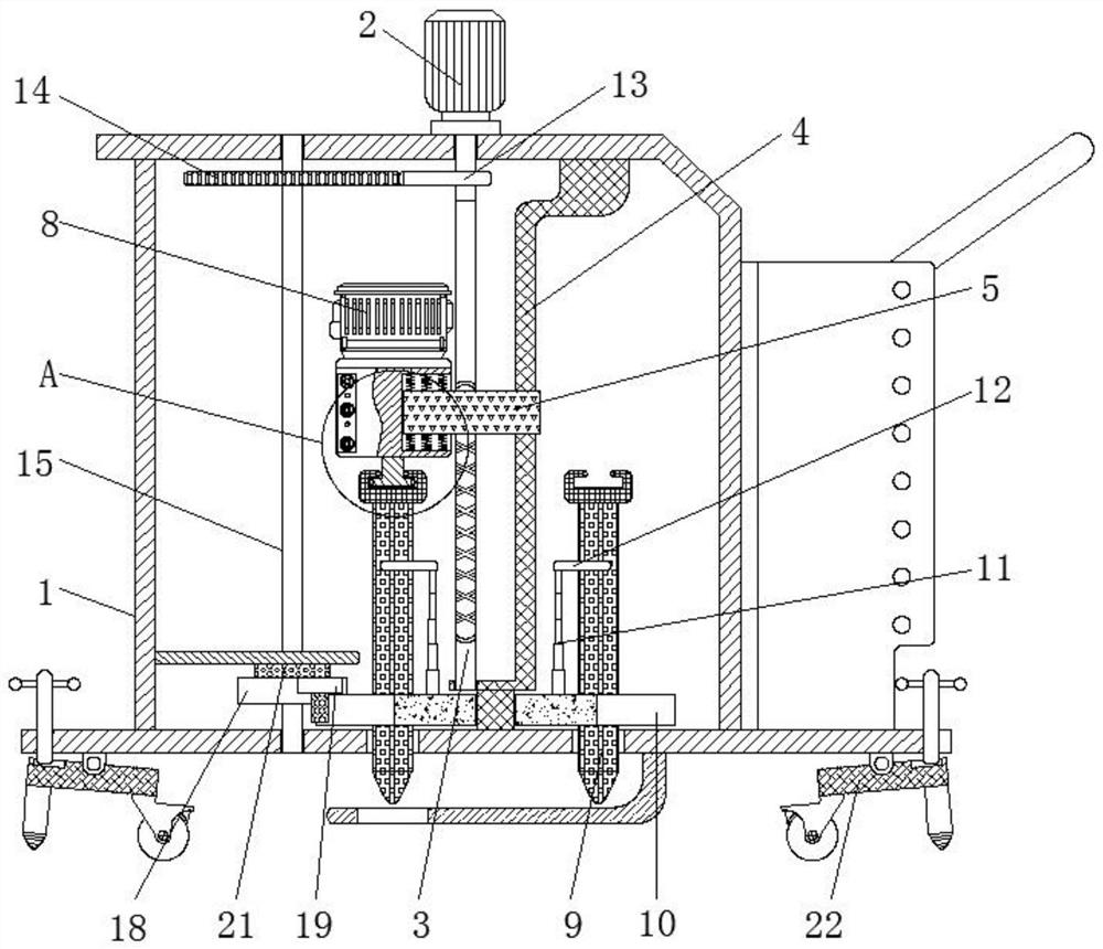
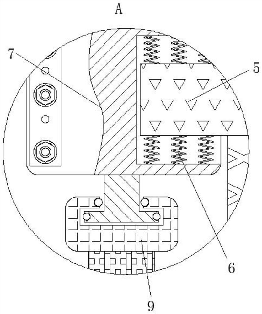
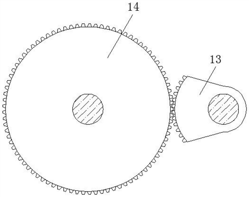
[0034] see Figure 1-6 , a mechanical sampling device for polluted soil layers, comprising a mobile frame 1, a stepping motor 2, a double threaded rod 3, a positioning rod 4, a threaded slider 5, a vibrating spring 6, a vibrating block 7, a vibrating machine 8, and a sampler 9 , positioning wheel 10, telescopic rod 11, block 12, sector gear 13, transmission gear 14, rotating shaft 15, lever 16, coil spring 17, turning block 18, shifting block 19, limiting bloc...


PUM


Abstract

The invention relates to the technical field of soil regeneration, and discloses a contaminated soil layer mechanical sampling device which comprises a moving frame. A stepping motor is fixedly connected to the top of the moving frame, a double-threaded rod is fixedly connected to the bottom of the stepping motor, and a positioning rod is movably connected to the exterior of the double-threaded rod. A threaded sliding block is movably connected to the exterior of the double-threaded rod, a vibration spring is fixedly connected to the interior of the threaded sliding block, and a vibration block is slidably connected to the interior of the threaded sliding block. Through the cooperative use of the double-threaded rod, the threaded sliding block, the vibration spring and the vibration block,the effect that the vibration block drives a sampler to vibrate is achieved; meanwhile, the threaded sliding block drives the sampler to move downwards, so that the sampling speed of the sampler is effectively increased, and the sampling work efficiency of the sampler is improved; after sampling is completed, the threaded sliding block automatically drives the sampler to ascend, and a vibrator iscontrolled to stop working in the ascending process, so that automatic operation is achieved, the operation difficulty is effectively reduced, and the work efficiency is improved.

Description

technical field [0001] The invention relates to the technical field of soil regeneration, in particular to a mechanical sampling device for polluted soil layers. Background technique [0002] During the long-term use of the soil, the soil is often polluted due to the destructive use of people and the discharge of a large amount of pollutants, which increases the harmful substances contained in the soil and exceeds the self-purification capacity of the soil, resulting in the loss of flowers, plants or crop products. The yield decreases, the quality decreases, and even harmful substances enter the human body through the farm crops, affecting the health of the eaters. [0003] In order to ensure the normal use of the soil, it is usually necessary to restore and regenerate the soil, and before the restoration and regeneration of the soil, it is necessary to choose different schemes according to the different pollution conditions of the soil, so before the regeneration of the soi...

Claims


Application Information

Patent Timeline
IPC IPC(8): G01N1/08
CPCG01N1/08
Inventor 吴思龙
Owner 吴思龙
Learn More