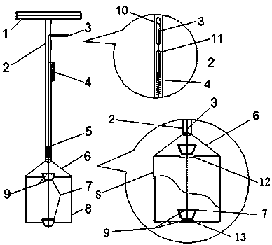
A deep tank slurry sampler
A sampler and pulp technology, applied in the field of deep groove pulp sampler, can solve the problems of inaccurate data detection results, poor sample representativeness, inconvenient extraction, etc. Effect
- Summary
- Abstract
- Description
- Claims
- Application Information
AI Technical Summary
Problems solved by technology
Method used
Image
Examples
Embodiment 1
[0014] Embodiment 1: as Fig. 1, a kind of deep groove slurry sampler, it comprises handle 1, hollow pipe 2, piston connecting rod 3, tension spring 4, piston connecting rod positioning block 5, connecting body 6, piston 7, The sampling cylinder 8 and the piston positioning block 9, the handle 1 and the hollow tube 2, the piston connecting rod positioning block 5, the connecting body 6, and the sampling cylinder 8 are connected as one, and the piston connecting rod 3 is connected as one with the piston 7 and the piston positioning block 9 , the upper end of the piston connecting rod 3 passes through the upper notch 10 on the side of the hollow tube for 10mm, the lower end of the tension spring 4 is fixed on the outer wall of the hollow tube 2, and the upper end is fixedly connected with the piston connecting rod 3 through the lower opening 11 on the side of the hollow tube 2, The piston connecting rod 3 passes through the piston connecting rod positioning block 5, and the piston...
Embodiment 2
[0015] Embodiment 2: as Fig. 1, a kind of deep groove slurry sampler, it comprises handle 1, hollow pipe 2, piston connecting rod 3, tension spring 4, piston connecting rod positioning block 5, connecting body 6, piston 7, The sampling cylinder 8 and the piston positioning block 9, the handle 1 is connected with the hollow tube 2, the piston connecting rod positioning block 5, the connecting body 6, and the sampling cylinder 8 as a whole, and the piston connecting rod 3 is connected with the piston 7 and the piston positioning block 9 as a whole , the upper end of the piston connecting rod 3 passes through the upper notch 10 on the side of the hollow tube by 8mm, the lower end of the tension spring 4 is fixed on the outer wall of the hollow tube 2, and the upper end is fixedly connected with the piston connecting rod 3 through the lower opening 11 on the side of the hollow tube 2, The piston connecting rod 3 passes through the piston connecting rod positioning block 5, and the ...
Embodiment 3
[0016] Embodiment 3: as Fig. 1, a kind of deep groove slurry sampler, it comprises handle 1, hollow pipe 2, piston connecting rod 3, tension spring 4, piston connecting rod positioning block 5, connecting body 6, piston 7, The sampling cylinder 8 and the piston positioning block 9, the handle 1 is connected with the hollow tube 2, the piston connecting rod positioning block 5, the connecting body 6, and the sampling cylinder 8, and the piston connecting rod 3 is connected with the piston 7 and the piston positioning block 9. , the upper end of the piston connecting rod 3 passes through the upper notch 10 on the side of the hollow tube for 12 mm, the lower end of the tension spring 4 is fixed on the outer wall of the hollow tube 2, and the upper end is fixedly connected with the piston connecting rod 3 through the lower opening 11 on the side of the hollow tube 2, The piston connecting rod 3 passes through the piston connecting rod positioning block 5, and the piston connecting ...
PUM
 Abstract
Description
Claims
Application Information
 - R&D
- Intellectual Property
- Life Sciences
- Materials
- Tech Scout
- Unparalleled Data Quality
- Higher Quality Content
- 60% Fewer Hallucinations
Browse by: Latest US Patents, China's latest patents, Technical Efficacy Thesaurus, Application Domain, Technology Topic, Popular Technical Reports.
© 2025 PatSnap. All rights reserved.Legal|Privacy policy|Modern Slavery Act Transparency Statement|Sitemap|About US| Contact US: help@patsnap.com

