
Magnetic induction sensor automatic test system and test method

A technology of a magnetic induction sensor and an automatic test system, applied in the field of sensor testing, can solve the problems such as the inability to meet the test use requirements, the low reliability of the test results, and the failure to be properly handled, so as to meet the needs of large-scale batch test use, and the test is stable and reliable. , the effect of high test efficiency

Pending Publication Date: 2021-01-01
苏州微测电子有限公司
View PDF13 Cites 0 Cited by
  • Summary
  • Abstract
  • Description
  • Claims
  • Application Information

AI Technical Summary

Problems solved by technology

At present, the function test of the magnetic induction sensor is usually carried out by manual detection. Each step takes a lot of time, it is difficult to carry out continuous operation, the degree of automation is low, not only the test efficiency is low, the test flexibility is low, and the test error is large. The reliability of the results is low, and it cannot meet the needs of large-scale testing.
In addition, the unqualified products obtained from the test are usually collected separately at will, and are not properly handled. It is easy to mix into qualified products due to operator errors, resulting in the outflow of unqualified products

Method used


Image

  • Magnetic induction sensor automatic test system and test method
  • Magnetic induction sensor automatic test system and test method
  • Magnetic induction sensor automatic test system and test method

Examples


Embodiment Construction

[0038] In order to explain the overall concept of the present invention more clearly, the following will be described in detail by way of examples in conjunction with the accompanying drawings.

[0039] In describing the present invention, it is to be understood that the terms "center", "upper", "lower", "front", "rear", "left", "right", "vertical", "horizontal", The orientation or positional relationship indicated by "top", "bottom", "inner", "outer", "axial", "radial" and "circumferential" are based on the orientation or positional relationship shown in the drawings, only It is for the convenience of describing the present invention and simplifying the description, but does not indicate or imply that the referred device or element must have a specific orientation, be constructed and operated in a specific orientation, and thus should not be construed as limiting the present invention.

[0040] In addition, the terms "first" and "second" are used for descriptive purposes only...


PUM


Abstract

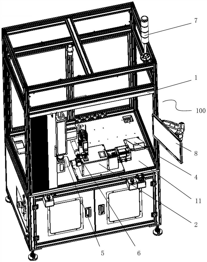
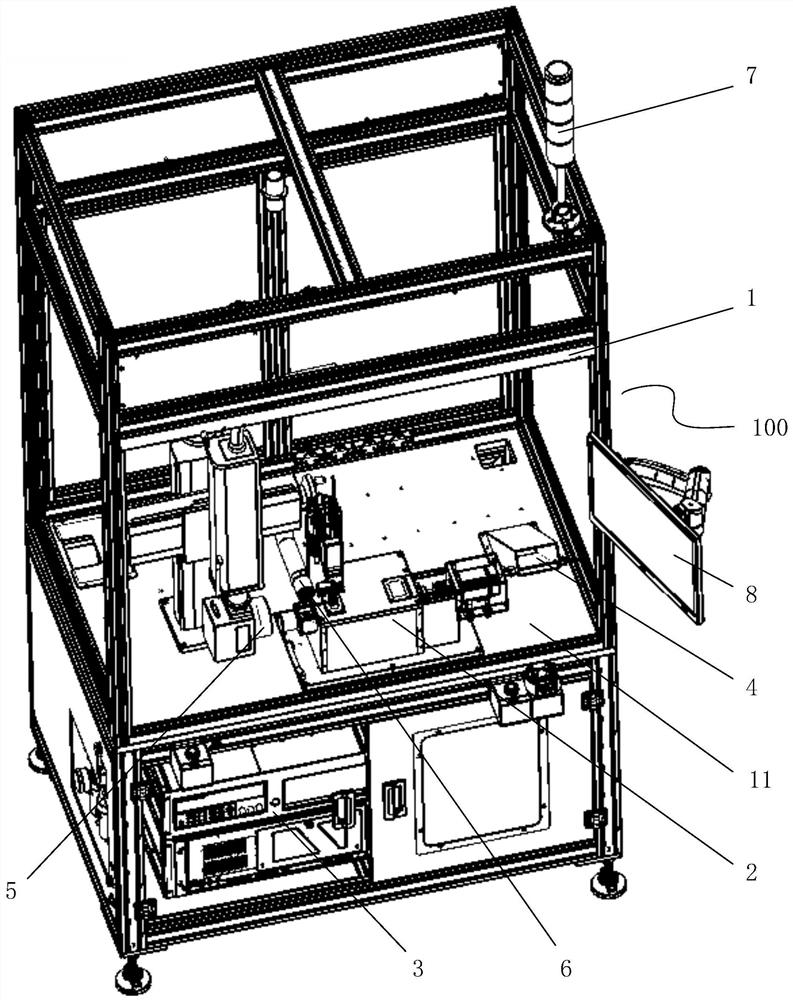
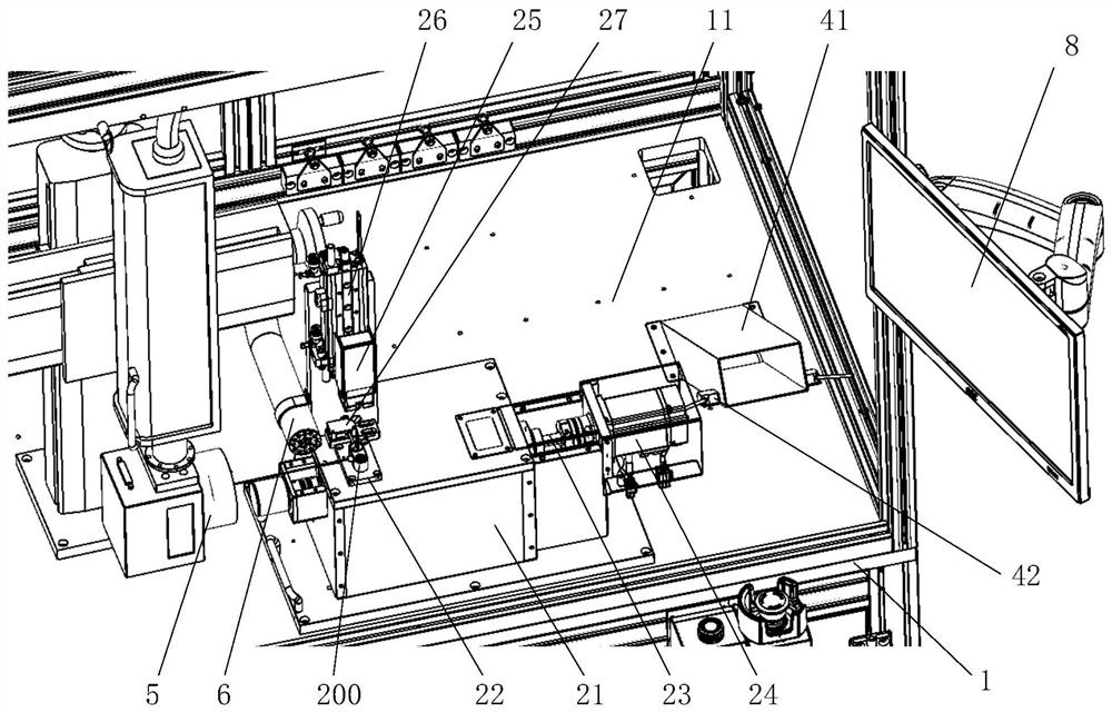
The invention discloses a magnetic induction sensor automatic test system and test method; the magnetic induction sensor automatic test system comprises a frame, a test module, a measurement and control module and an inferior-quality product recovery module, and the frame is provided with a test platform; the test module comprises a mounting frame, a sensor clamp, a test body and a test driving device, the mounting frame is fixedly arranged at the top of the test platform, the sensor clamp is fixedly arranged at the top of the mounting frame and used for fixedly placing a to-be-tested magneticinduction sensor, the test body is movably arranged on the mounting frame, and the test body can be provided with a magnetic part; the test driving device is in transmission connection with a test body and can drive the test body to move relative to the mounting frame so as to drive the magnetic part to move relative to the sensor clamp; the measurement and control module is connected with the test driving device and can be detachably connected with the magnetic induction sensor; the inferior-quality product recovery module is provided with an inferior-quality product recovery inlet and an inferior-quality product detection device. The inferior-quality product detection device is arranged at the inferior-quality product recovery inlet and connected with the measurement and control module.

Description

technical field [0001] The invention belongs to the technical field of sensor testing, in particular to an automatic testing system and testing method for a magnetic induction sensor. Background technique [0002] The magnetic induction sensor uses the magnetic field as the medium, has the characteristics of non-contact, low power consumption, high reliability, long service life and high response frequency, so it is widely used. Before leaving the factory, the magnetic induction sensor must be quantitatively tested for its main performance parameters to ensure the performance reliability of the product. At present, the function test of the magnetic induction sensor is usually carried out by manual detection. Each step takes a lot of time, it is difficult to carry out continuous operation, the degree of automation is low, not only the test efficiency is low, the test flexibility is low, and the test error is large. The result is low reliability and cannot meet the needs of m...

Claims


Application Information

Patent Timeline
IPC IPC(8): G01R35/00
CPCG01R35/00G01R33/0023
Inventor 欧阳胜红谢永刚柳元富
Owner 苏州微测电子有限公司
Learn More