

Laser-radar-based traffic light device and system
A technology of laser radar and traffic lights, which is applied in location information-based services, road vehicle traffic control systems, traffic control systems, etc., to improve road traffic capacity, reduce failure rate, facilitate traffic flow and road condition analysis
- Summary
- Abstract
- Description
- Claims
- Application Information
AI Technical Summary
Problems solved by technology
Method used
Image

Examples
Embodiment 1
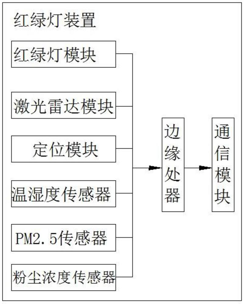
[0046] Such as figure 1 As shown, a kind of traffic light device based on laser radar of the present invention comprises traffic light module, laser radar module, positioning module, edge processing module communication module and shell, and traffic light module, laser radar module, positioning module are all connected with edge processor Electrically connected, the edge processor is electrically connected to the communication module, and the housing encapsulates the above-mentioned traffic light module, laser radar module, positioning module, edge processor and communication module into a set of devices.
[0047] The traffic light module is a conventional traffic light module, which can display traffic light status and time information. This module can obtain its own traffic light status to form traffic light information, and send the traffic light information to the edge processor.
[0048] The laser radar module is used to measure the position, motion state and shape of the...
Embodiment 2
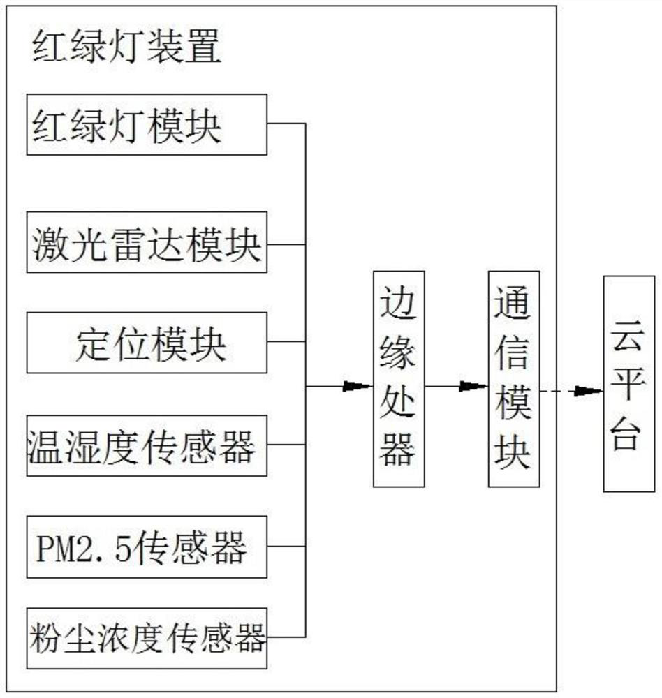
[0056] Such as figure 2 As shown, the traffic light system based on laser radar in the present invention includes a traffic light device and a cloud platform. The effective scanning areas of the modules are not repeated, and the scanning area of one of the laser radar modules can cover the scanning blind area of the other laser radar module; the cloud platform is wirelessly connected with the above-mentioned traffic light device.
[0057] The cloud platform is used to perform the following operations:
[0058] Storing and parsing the monitoring information, generating a traffic light system management table, the traffic light system management table includes traffic light position information, traffic flow information and fault information, and the above information is bound to time respectively;
[0059] Carry out road condition analysis based on real-time traffic flow information and historical data of the traffic light system management table, conduct traffic predicti...
PUM
 Abstract
Description
Claims
Application Information