Memory testing method, memory chip and memory system

A technology for memory testing and memory chips, applied in static memory, instruments, etc., can solve the problems of not fully discovering DRAM performance limits, DRAM reliability decline, DRAM errors, etc., to achieve efficient classification testing, best performance, and saving testing time. Effect

Active Publication Date: 2021-01-01
XI AN JIAOTONG UNIV +1
View PDF10 Cites 2 Cited by
  • Summary
  • Abstract
  • Description
  • Claims
  • Application Information

AI Technical Summary

Problems solved by technology

In order to ensure no errors, the existing method needs to reserve a certain margin even after finding a more aggressive parameter setting, and cannot fully discover the

Method used


Image

  • Memory testing method, memory chip and memory system
  • Memory testing method, memory chip and memory system
  • Memory testing method, memory chip and memory system

Examples


Embodiment 1

[0079] Process:

[0080] Process drift generally exists in different batches of wafers and chips in different positions on the same wafer. Although the product standard is unified, it must be able to meet all chips in different batches and locations, but for chips or areas whose performance is degraded due to process drift, only looser parameter settings can be supported; otherwise, more aggressive parameters can be applied.

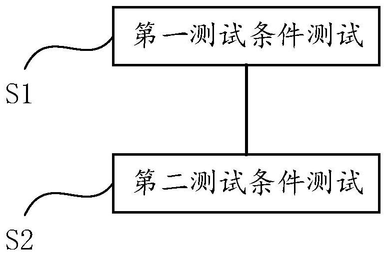
[0081] For the test of process parameters, the performance is mainly caused by the different positions of the chips on the wafer. That is, a good area or a non-good area under different processes. Chips in good areas perform better; otherwise, they perform poorly. Therefore, different test conditions can be set as the position parameters of the chip on the wafer. For example, the chip performance on the edge of the wafer (ie: non-good area) is usually poor, so the position of the non-edge area can be set as the first test. For the conditional test, th...

Embodiment 2

[0087] Voltage:

[0088] Due to the uncertainty of the working environment, there must be various fluctuations in the power supply of DRAM, including long-term voltage drop and short-term power supply noise. Power supply fluctuations have a huge impact on the performance of DRAM. For example, when the DRAM power supply is low due to the resistance of the power supply network itself, the data in the DRAM is more prone to errors. Another example is when continuous data throughput is performed, due to the power supply noise brought by the input and output circuits, the data in the DRAM is also more prone to errors. In order to cover the impact of the above power fluctuations, it is necessary to set appropriate voltage parameters for testing.

[0089] For the voltage test, supply voltages with different performances can be set, for example, the simplest, the voltage value of the first test condition is greater than the voltage value of the second test condition. In a DRAM chip, ...

Embodiment 3

[0095] temperature:

[0096]The impact on DRAM chips is that on the one hand, the increase in leakage current caused by high temperature will reduce the retention time of DRAM and require a shorter refresh time. On the other hand, high temperature or low temperature will reduce the performance of peripheral circuits, resulting in increased operation delay.

[0097] Similar to the voltage, different test conditions will be set according to the influence of the DRAM chip working at different temperatures. The test conditions here can be divided into two aspects.

[0098] The first aspect: different temperature settings are made according to the difference in leakage caused by the temperature of the storage unit in the DRAM chip; it should be noted that the leakage will increase with the increase of temperature. So the higher the temperature, the looser the test conditions.

[0099] The second aspect: Combining the influence of the performance and temperature of the peripheral ...


PUM


Abstract

The invention discloses a memory testing method, a memory chip and a memory system, and the testing method comprises the steps: carrying out the testing of different testing conditions according to different performances of the memory chip, wherein at least two different test conditions are provided. The different test conditions at least comprise a first test condition and a second test condition; the second test condition is stricter than the first test condition. The method has the advantages that different test conditions are subjected to classification test, and different tests and classifications are performed according to the difficulty degrees of the different test conditions and the influence degrees on the performance of the chip, so that on one hand, the chip can be subjected toefficient classification test, the test time and the test cost are saved, and the test efficiency is improved; on the other hand, the performance of the memory can be brought into full play, and theoptimal performance of the memory chip under specific test conditions is explored.

Description

technical field [0001] The invention belongs to the field of electronic circuits, and in particular relates to a memory testing method, a memory chip and a memory system. Background technique [0002] In order to ensure that DRAM can work correctly under all circumstances, DRAM manufacturers generally use the worst case (worst case) for testing and screening. In fact, when most units work under common case (common case), they can have a faster operating frequency or a higher frequency. low power consumption. [0003] On the one hand, in order to reduce power consumption, one method can reduce the refresh frequency, and the other method can reduce the power supply voltage of the array. [0004] On the other hand, for a higher operating frequency, by studying the influence of temperature and process deviation on important timing parameters, the timing parameters can be further compressed to improve system performance. Or analyze the deviation brought by the DRAM design itsel...

Claims


Application Information

Patent Timeline
IPC IPC(8): G11C29/50G11C29/12
CPCG11C29/50G11C29/12005G11C2029/5004G11C2029/5002
Inventor 拜福君孙宏滨
Owner XI AN JIAOTONG UNIV
Why Eureka
Try Eureka