Stirring mechanism of emulsifying machine for cosmetic production

A stirring mechanism and emulsifying machine technology, applied in the direction of mixer accessories, mixers with rotating stirring devices, mixers, etc., can solve the problems such as the decrease of the seal between the pot body and the pot cover, the inability to stir the pot body, and the sticking of raw materials to the wall. Achieve the effects of improving the emulsification effect, increasing the maximum radius of gyration, and increasing the stirring resistance

Inactive Publication Date: 2021-01-05
济南艾雅贸易有限公司
View PDF7 Cites 3 Cited by
  • Summary
  • Abstract
  • Description
  • Claims
  • Application Information

AI Technical Summary

Problems solved by technology

[0002] The emulsification pot of the vacuum emulsification machine is mainly divided into two parts: the pot cover and the pot body. The pot body and the pot cover adopt a detachable design. During the emulsification operation, there is a negative pressure between the pot body and the inside of the pot cover. The sealing performance of the pot body generally reduces the opening area of ​​the pot body, that is, the opening diameter of the pot body is smaller than the internal diameter, so the maximum turning radius of the stirring mechanism needs to be smaller than the opening diameter o

Method used


Image

  • Stirring mechanism of emulsifying machine for cosmetic production
  • Stirring mechanism of emulsifying machine for cosmetic production
  • Stirring mechanism of emulsifying machine for cosmetic production

Examples


Embodiment Construction

[0025] The following will clearly and completely describe the technical solutions in the embodiments of the present invention with reference to the accompanying drawings in the embodiments of the present invention. Obviously, the described embodiments are only some, not all, embodiments of the present invention. Based on the embodiments of the present invention, all other embodiments obtained by persons of ordinary skill in the art without making creative efforts belong to the protection scope of the present invention.

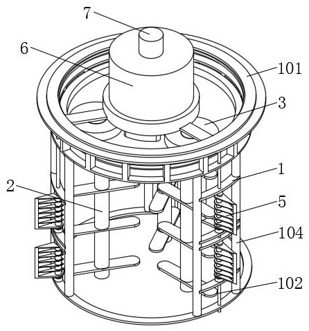
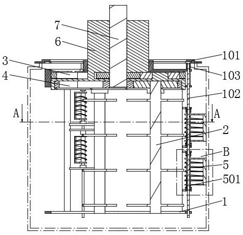
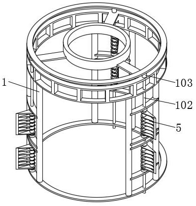
[0026] see Figure 1-7 , the present invention provides a technical solution: a stirring mechanism of an emulsifying machine for cosmetics production, including a fixed seat 6, and the external coaxial rotation of the fixed seat 6 is provided with a first stirring mechanism 1 and a second stirring mechanism 2, and the first stirring mechanism 1 Contrary to the rotation direction of the second stirring mechanism 2, the first stirring mechanism 1 includes a scra...


PUM


Abstract

The invention discloses a stirring mechanism of an emulsifying machine for cosmetic production, which comprises a fixed seat, a first stirring mechanism and a second stirring mechanism are coaxially and rotatably arranged outside the fixed seat, the rotation directions of the first stirring mechanism and the second stirring mechanism are opposite, the first stirring mechanism comprises a scraper frame with a rotary structure, a long shaft capable of being vertically pulled is arranged in the circumferential wall of the scraper frame, a circular ring is fixedly arranged at the upper end of thelong shaft, a first elastic piece is arranged between the circular ring and the scraper frame, the rotation axis of the circular ring and the rotation axis of the scraper frame are overlapped, and a coaxial movable ring is connected to the upper portion of the circular ring in a relatively rotating mode, the turning radius of the movable ring is greater than that of the scraper frame, and a scraper is arranged in the scraper frame. According to the stirring mechanism of the emulsifying machine for cosmetic production, due to the design of the foldable scraping plates, the turning radius is reduced after the stirring mechanism is folded, the stirring mechanism can conveniently pass through an opening of a pot body with a small hole diameter, and the scraping and stirring requirements of rawmaterials on the inner wall of the pot body are met after the stirring mechanism is unfolded; the design of reducing the opening diameter of the pot body is facilitated, and the sealing performance of the emulsifying pot is improved.

Description

technical field [0001] The invention relates to the technical field of cosmetic production equipment, in particular to a stirring mechanism of an emulsifier for cosmetic production. Background technique [0002] The emulsification pot of the vacuum emulsification machine is mainly divided into two parts: the pot cover and the pot body. The pot body and the pot cover adopt a detachable design. During the emulsification operation, there is a negative pressure between the pot body and the inside of the pot cover. The sealing performance of the pot body generally reduces the opening area of ​​the pot body, that is, the opening diameter of the pot body is smaller than the internal diameter, so the maximum turning radius of the stirring mechanism needs to be smaller than the opening diameter of the pot body, resulting in the part of the pot body close to the side wall cannot be stirred , and there is a problem of raw material sticking to the wall, which is difficult to remove. The...

Claims


Application Information

Patent Timeline
IPC IPC(8): B01F15/00B01F7/30B01F7/24B01F7/18B01F3/08
CPCB01F23/41B01F27/1921B01F27/2322B01F27/85B01F27/922B01F27/951B01F27/90B01F35/00B01F35/123B01F2035/351B01F2101/21
Inventor 不公告发明人
Owner 济南艾雅贸易有限公司
Why Eureka
Try Eureka