Ring forming device for silver strips
A strip-shaped and ring-forming technology, which is applied in the direction of pushing out equipment, metal processing equipment, feeding devices, etc., can solve the problem that the ringing of silver bars cannot ensure uniform ringing, and achieve the optimal ringing effect, uniform ringing, and Beautiful effect of silver bars
- Summary
- Abstract
- Description
- Claims
- Application Information
AI Technical Summary
Problems solved by technology
Method used
Image

Examples
Embodiment 1
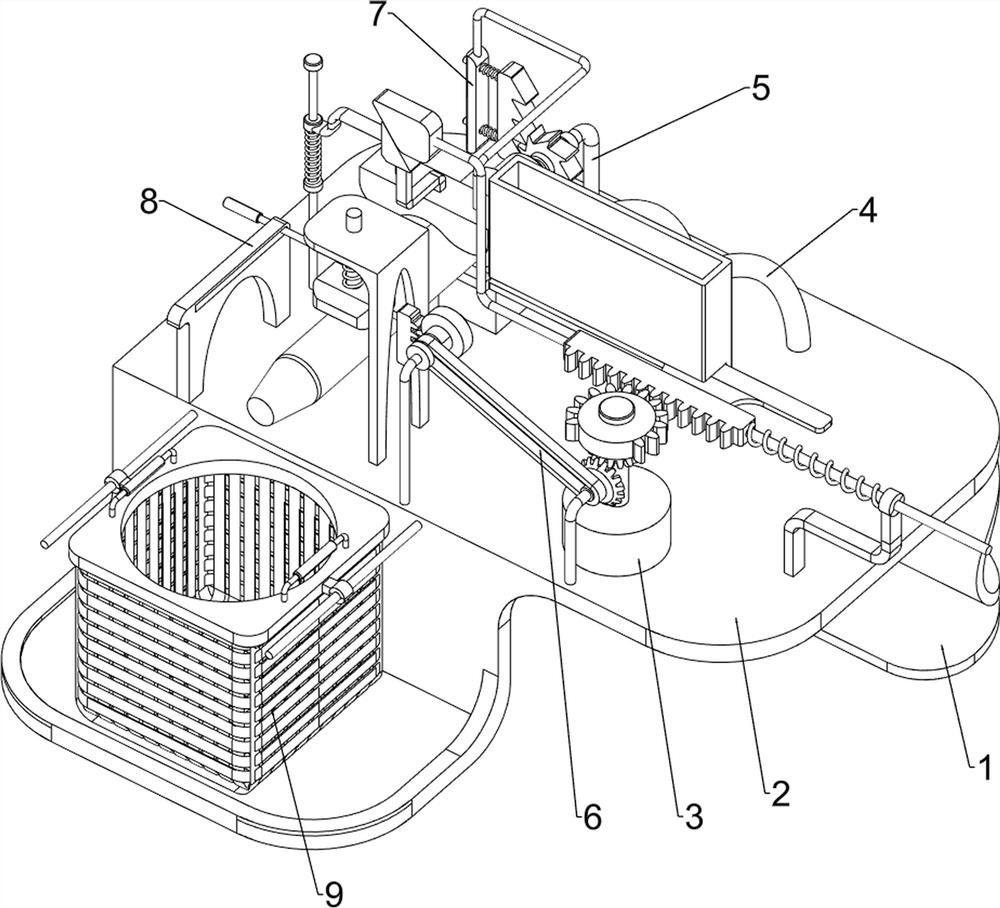
[0030]A kind of equipment used to form silver bars, such asfigure 1 ,figure 2 ,image 3 As shown, it includes a fixed support 1, a workbench 2, a motor 3, a feeding mechanism 4, and a bending mechanism 5. The fixed support 1 is provided with a workbench 2, the workbench 2 is equipped with a motor 3, and the workbench 2 is provided with The feeding mechanism 4 is provided with a bending mechanism 5 on the left side of the worktable 2.
[0031]First place the silver bars that need to be looped on the feeding mechanism 4, turn on the motor 3, and when the output shaft of the motor 3 rotates, the feeding mechanism 4 will be driven, and the operation of the feeding mechanism 4 will drive the bending mechanism 5 to operate. To achieve the purpose of looping the silver bars, when the looping is completed, the motor 3 is turned off. When the output shaft of the motor 3 stops rotating, the feeding mechanism 4 will stop operating, and the stopping of the feeding mechanism 4 will cause the bending...
Embodiment 2
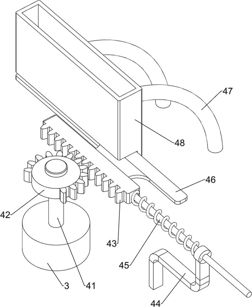
[0033]On the basis of Example 1, such asfigure 1 ,figure 2 ,image 3 As shown, the feeding mechanism 4 includes a first rotating shaft 41, a first missing gear 42, a first rack 43, a first bearing column 44, a first telescopic assembly 45, a first push plate 46, a first fixing column 47 and a placement Box 48, the output shaft of the motor 3 is provided with a first rotating shaft 41, a first missing gear 42 is provided on the first rotating shaft 41, a first bearing column 44 is provided on the right side of the worktable 2, and the first bearing column 44 slides on it The first rack 43 is provided with a first rack 43 that meshes with the first gear 42. The first rack 43 is sleeved with a first telescopic assembly 45. The right side of the first telescopic assembly 45 is connected to the first bearing column 44 , The rear side of the first rack 43 is provided with a first push plate 46, the upper and rear side of the workbench 2 is provided with a first fixed column 47, the first f...
Embodiment 3
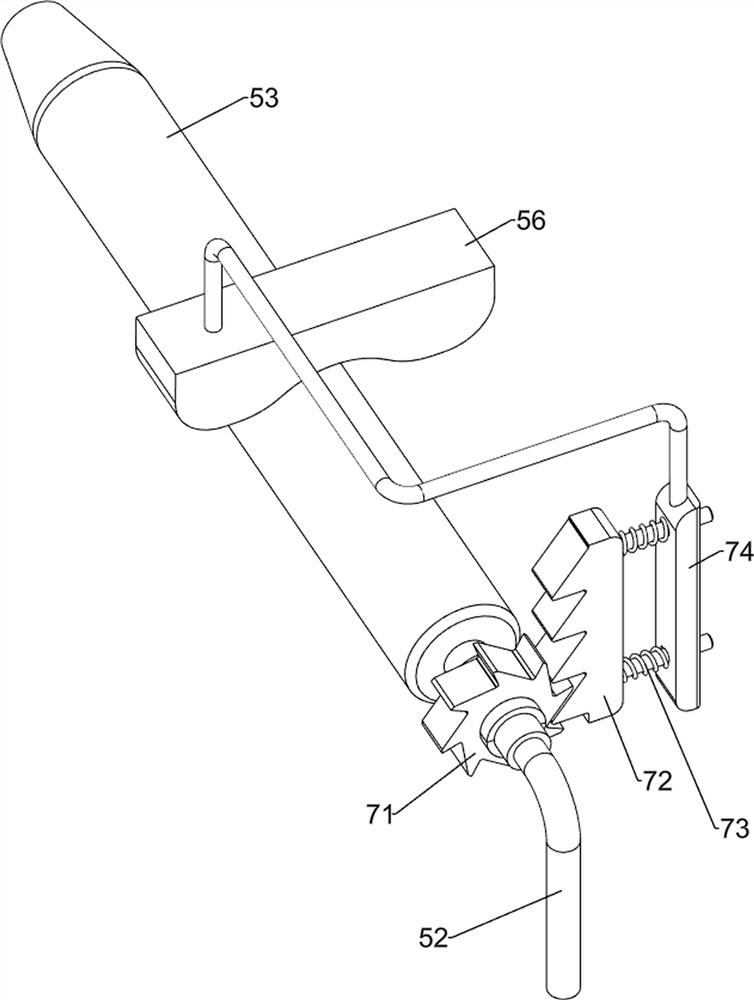
[0038]On the basis of Example 2, such asFigure 4 ,Figure 5 ,Figure 6 ,Figure 7As shown, it also includes a beating mechanism 6. The worktable 2 is provided with a beating mechanism 6 on the front side. The beating mechanism 6 includes a fourth fixed column 61, a bevel gear assembly 62, a fifth fixed column 63, a transmission assembly 64, The second gear 65, the second rack 66, the beating plate 67, the first fixing plate 68 and the third telescopic assembly 69, the workbench 2 is provided with a fourth fixing column 61, a fourth fixing column 61 and a first rotating shaft on the front side A bevel gear assembly 62 is provided between 41, a fifth fixed column 63 is provided on the front side of the worktable 2, and a second missing gear 65 is rotatably provided on the fifth fixed column 63, the second missing gear 65 and the bevel gear There is a transfer assembly 64 between the assemblies 62, a first fixing plate 68 is provided on the left side of the workbench 2, a third telescopic...
PUM
 Abstract
Description
Claims
Application Information
 - R&D
- Intellectual Property
- Life Sciences
- Materials
- Tech Scout
- Unparalleled Data Quality
- Higher Quality Content
- 60% Fewer Hallucinations
Browse by: Latest US Patents, China's latest patents, Technical Efficacy Thesaurus, Application Domain, Technology Topic, Popular Technical Reports.
© 2025 PatSnap. All rights reserved.Legal|Privacy policy|Modern Slavery Act Transparency Statement|Sitemap|About US| Contact US: help@patsnap.com