Numerical control metal cutting machine tool based on cutting fluid recycling

A metal cutting and cutting fluid technology, applied in the direction of metal processing machinery parts, metal processing equipment, maintenance and safety accessories, etc., can solve the problems of inconvenient centralized cleaning, reduce the efficiency of filtration, and increase costs, so as to facilitate centralized cleaning and reduce Effect of friction and efficiency improvement

Inactive Publication Date: 2021-01-05
广州市珂迪兹皮具有限公司
View PDF7 Cites 1 Cited by
  • Summary
  • Abstract
  • Description
  • Claims
  • Application Information

AI Technical Summary

Problems solved by technology

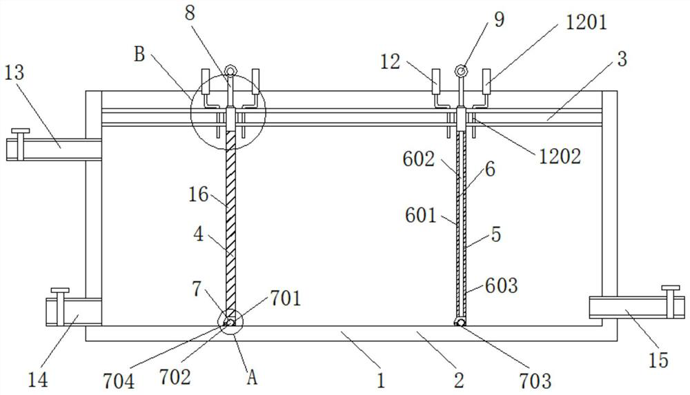
[0005] The object of the present invention is to solve the problem that it is difficult to adjust the filtering space of the filter tank according to the content of the cutting fluid when the existing cutting waste liquid treatment tank is filtering the cutting fluid, so that the space occupied by the waste liquid is relatively large. It is impossible to directly concentrate the slag in the waste liquid inside the treatment tank, which is not convenient for centralized cleaning in the later stage, thus reducing the filtration efficiency to a certain extent, and when the existing treatment tank adjusts the position of the filter screen, Generally, it is necessary to completely drain the liquid inside the treatment tank, then remove the filter screen and reinstall it, which reduces the efficiency of its adjustment to a certain extent, and makes its installation structure more complicated and increases the cost. problem, provide a CNC metal cutting machine tool based on recycling of cutting fluid

Method used


Image

  • Numerical control metal cutting machine tool based on cutting fluid recycling
  • Numerical control metal cutting machine tool based on cutting fluid recycling
  • Numerical control metal cutting machine tool based on cutting fluid recycling

Examples


Embodiment Construction

[0026] The following will clearly and completely describe the technical solutions in the embodiments of the present invention with reference to the accompanying drawings in the embodiments of the present invention. Obviously, the described embodiments are only some, not all, embodiments of the present invention. Based on the embodiments of the present invention, all other embodiments obtained by persons of ordinary skill in the art without making creative efforts belong to the protection scope of the present invention.

[0027] In the description of the present invention, it should be noted that the terms "center", "upper", "lower", "left", "right", "vertical", "horizontal", "inner", "outer" etc. The indicated orientation or positional relationship is based on the orientation or positional relationship shown in the drawings, and is only for the convenience of describing the present invention and simplifying the description, rather than indicating or implying that the referred d...


PUM


Abstract

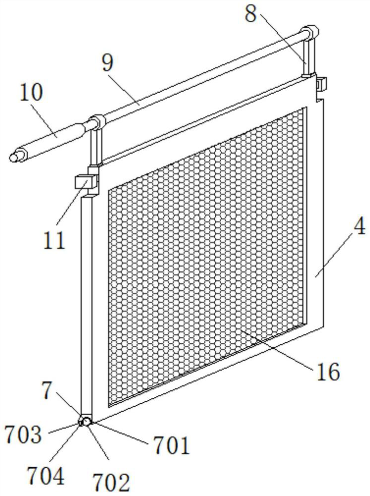
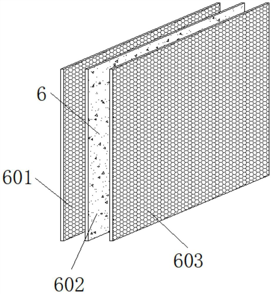
The invention discloses a numerical control metal cutting machine tool based on cutting fluid recycling, and belongs to the technical field of numerical control machine tools. The numerical control metal cutting machine tool comprises a structure body, wherein a collecting groove is formed in the outer side of the structure body, sliding grooves are formed in the tops of the two ends of the innerside of the collecting groove, and a first supporting frame is arranged on one sides of the adjacent ends of the two sliding grooves; and a second supporting frame is arranged on one side of the firstsupporting frame, and a filter screen is arranged on the inner side of the first supporting frame. When the first supporting frame or the second supporting frame moves leftwards or rightwards, rolling rods at the bottom of the first supporting frame or the second supporting frame roll in the sliding grooves so that the first supporting frame and the second supporting frame can be supported, meanwhile, more labor is saved during sliding of the first supporting frame and the second supporting frame, friction force is reduced, thus, the space occupied by waste liquid is adjusted, residues in thewaste liquid can be directly concentrated in a treatment tank, later centralized cleaning is facilitated, and the filtering efficiency is improved to a certain extent.

Description

technical field [0001] The invention relates to the technical field of numerical control machine tools, in particular to a numerical control metal cutting machine tool based on recycling of cutting fluid. Background technique [0002] Metal cutting is a method of material removal and forming in the metal forming process. It still occupies a large proportion in today's mechanical manufacturing. The metal cutting process is a process of interaction between the workpiece and the tool. The tool removes excess metal from the workpiece to be processed. And under the premise of controlling productivity and cost, the workpiece can obtain the geometric accuracy, dimensional accuracy and surface quality that meet the design and process requirements. In order to realize this process, there must be relative motion between the workpiece and the tool, that is, cutting motion, which consists of Metal cutting machine tools are provided, machine tools, fixtures, tools and workpieces constitu...

Claims


Application Information

Patent Timeline
Patent Type & Authority Applications(China)
IPC IPC(8): B23Q11/00B01D46/00
CPCB01D46/00B23Q11/0042
Inventor 陈亮
Owner 广州市珂迪兹皮具有限公司
Why Eureka
Try Eureka