Mechanical part surface sand blasting device

A technology for surface sandblasting and mechanical parts, applied in the field of mechanical parts, can solve the problems of poor chip removal effect, different cleaning effect, difficult speed control, etc., to achieve the effect of being conducive to reuse, separation, and high degree of automation

Active Publication Date: 2021-01-05
山西衡兴盛机械设备股份有限公司
View PDF6 Cites 2 Cited by
  • Summary
  • Abstract
  • Description
  • Claims
  • Application Information

AI Technical Summary

Problems solved by technology

However, most of the current sandblasting devices have a fixed position of the nozzle, and the parts need to be manually moved to perform full sandblasting on the parts. Since the speed of manual movement is not easy to control, the cleaning effect of the sand flow on different parts of the parts is different, and the dust removal effect is not good. good
At the same time, the used sand and gravel are usually mixed with the iron filings impacted from the surface of the parts. In order to reuse the sand and gravel, it is usually necessary to separate the sand and gravel from the iron filings. However, due to the large amount of iron filings in the mixture, this requires It takes extra time for centralized cleaning, and the separation operation cannot be performed while the sand blasting device is in operation, and the operation is not convenient enough

Method used


Image

  • Mechanical part surface sand blasting device
  • Mechanical part surface sand blasting device
  • Mechanical part surface sand blasting device

Examples


Embodiment Construction

[0019] The following will clearly and completely describe the technical solutions in the embodiments of the present invention with reference to the accompanying drawings in the embodiments of the present invention. Obviously, the described embodiments are only some, not all, embodiments of the present invention. Based on the embodiments of the present invention, all other embodiments obtained by persons of ordinary skill in the art without making creative efforts belong to the protection scope of the present invention.

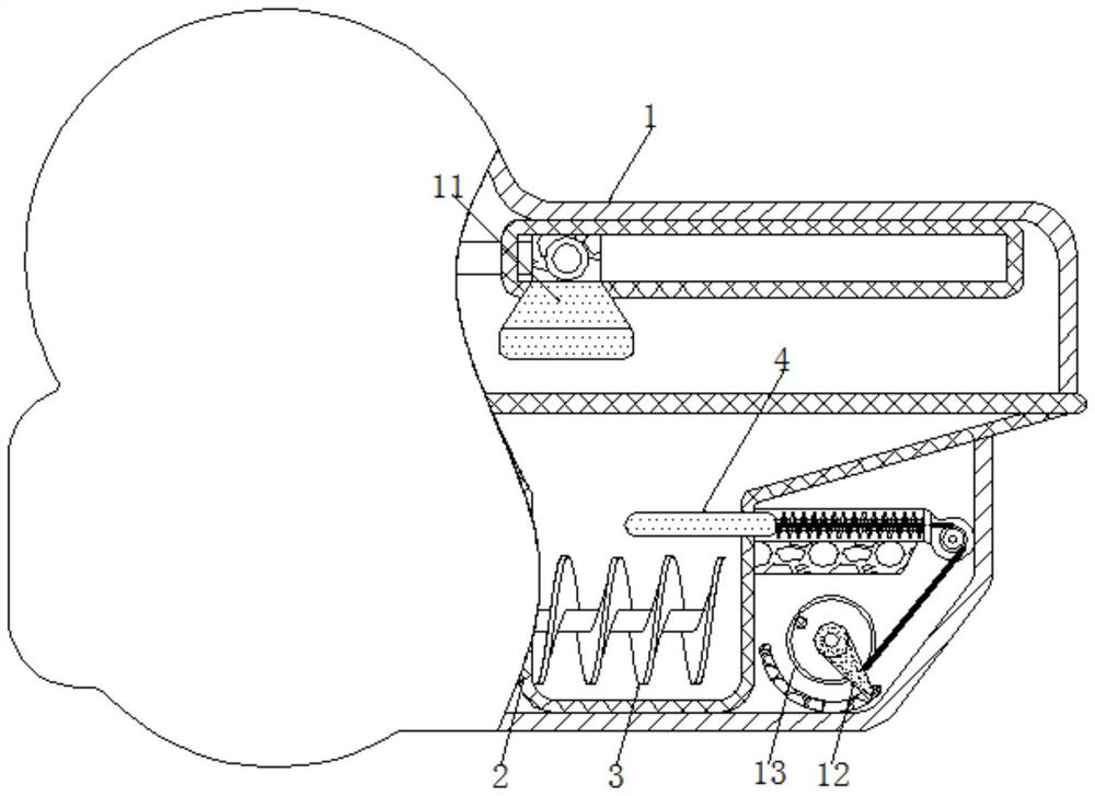
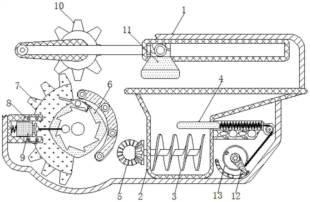
[0020] see Figure 1-3 , a sandblasting device for the surface of mechanical parts, comprising a shell 1, the inside of the shell 1 is fixedly connected with a collection bin 2, the top of the collection bin 2 is fixedly connected with an operation table, and the right side of the collection bin 2 is fixedly connected with a groove plate, the groove plate There is a card groove on the surface of the groove plate, and the waste bin is fixedly connected to the b...


PUM


Abstract

The invention relates to the technical field of mechanical parts, and discloses a mechanical part surface sand blasting device. The device comprises a shell, and a collecting bin is fixedly connectedto the interior of the shell. According to the device, automatic linear moving sand blasting is conducted, so that the moving speed is kept consistent, two hands are liberated, and the situation thatduring manual operation, the moving speed is not constant, and consequently the scrap removing degree is not uniform is avoided; by means of the capacitance principle, the magnetic state of an attraction tool is controlled, so that the scrap removing operation is conveniently conducted, the linkage between structures is improved, and the high automation degree is achieved; a mixture of sandstone and scrap iron is stored and turned over, so that the scrap iron in the mixture is conveniently attracted by the attraction tool, the sandstone is separated from the scrap iron, and the sandstone can be conveniently recycled; and the attraction tool attracting the scrap iron is automatically moved out of the collecting bin, by means of the property of an electromagnet, the attraction tool losing magnetism does not attract the scrap iron any more, the scrap iron automatically falls off under the action of the gravity of the scrap iron, and the scrap iron is intensively collected.

Description

technical field [0001] The invention relates to the technical field of mechanical parts, in particular to a sandblasting device for the surface of mechanical parts. Background technique [0002] The service life of mechanical parts is long. During use, most parts will be rusted by the action of air. Continuous use of such parts will not only reduce the working performance of the equipment, but also shorten the service life of the parts. To avoid In such a situation, to maximize the use of parts, the surface of the part is usually sandblasted with the aid of a sandblasting device. The high-speed sand flow impacts and cuts the surface of the part, improving the mechanical properties of the part surface. However, most of the current sandblasting devices have a fixed position of the nozzle, and the parts need to be manually moved to perform full sandblasting on the parts. Since the speed of manual movement is not easy to control, the cleaning effect of the sand flow on different...

Claims


Application Information

Patent Timeline
Patent Type & Authority Applications(China)
IPC IPC(8): B24C3/06B24C9/00B03C1/30
CPCB03C1/30B24C3/06B24C9/00B24C9/006
Inventor 张翼翔
Owner 山西衡兴盛机械设备股份有限公司
Why Eureka
Try Eureka