Integrated C-ring structure

An integrated, skeleton technology, applied in the field of auto parts, can solve the problems of complex design of the C-ring structure, road noise level, durability safety and vehicle handling stability performance, cost, energy, weight increase and other problems are not avoided , to reduce the development and design cycle and cost, excellent electromagnetic shielding performance, increase cost and weight

Active Publication Date: 2021-01-05
ZHEJIANG GEELY HLDG GRP CO LTD +1
View PDF8 Cites 0 Cited by
  • Summary
  • Abstract
  • Description
  • Claims
  • Application Information

AI Technical Summary

Problems solved by technology

[0003] The traditional C-ring structure involves many parts and connection points. The current design mostly assembles the parts together by welding or riveting between steel plates, which leads to a more complex overall structure, cumbersome connection process, and requires many Auxiliary stamping dies and welding fixtures cause a waste of human resources and energy; at the same time, the traditional C-ring structure often has weak structures, resulting in insufficient torsional rigidity of the car, which in turn causes road noise levels, durability, safety and car handling The decline in stability performance directly affects people's recognition of car quality
[0004] The traditional method to solve the above technical problems is to increase the torsional stiffness of the C-ring structure by adding reinforcement plates, and in order to ensure the key role of the introduction of reinforcement plates, the number, cross-section and thickness of reinforcement plates are often increased, directly sacrificing the Cost, development cycle, light weight, vehicle space layout and other performance, while not avoiding the current complex design problems of the C-ring structure, the overall improvement effect is not obvious
In addition, the traditional design will also reduce the impact of road noise by adding sound insulation or sound-absorbing materials in the noise transmission path. This will undoubtedly increase the number of stamping dies and assembly tools, directly resulting in an increase in cost, energy, weight, etc. High cost performance, low power consumption, and lightweight design development increase resistance

Method used


Image

  • Integrated C-ring structure
  • Integrated C-ring structure
  • Integrated C-ring structure

Examples


Embodiment Construction

[0027] The specific implementation manners of the present invention will be further described in detail below in conjunction with the accompanying drawings and embodiments. The following examples are used to illustrate the present invention, but are not intended to limit the scope of the present invention.

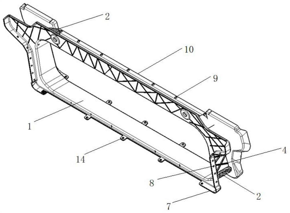
[0028] Such as figure 1 , figure 2 As shown, the integrated C-ring structure of the present invention includes a skeleton 1 and a foamed aluminum material, and the skeleton 1 is integrally formed into a C-ring by injection molding of nylon 66 and 50% glass fiber material (nylon 66 with a glass fiber content of 50) The structure replaces the welding and riveting structure of many parts of the original C-ring structure, which satisfies lightweight and effectively reduces the development and design cycle and cost.

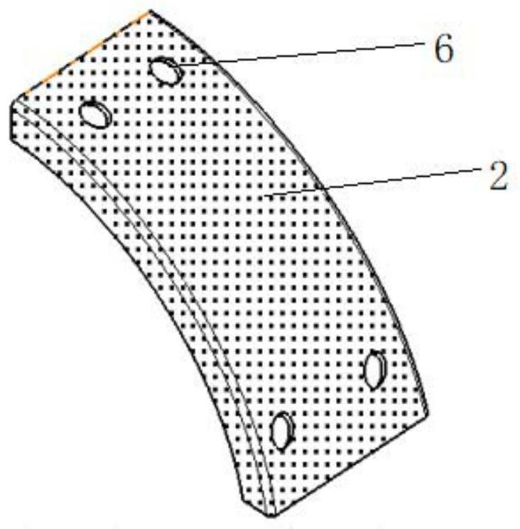
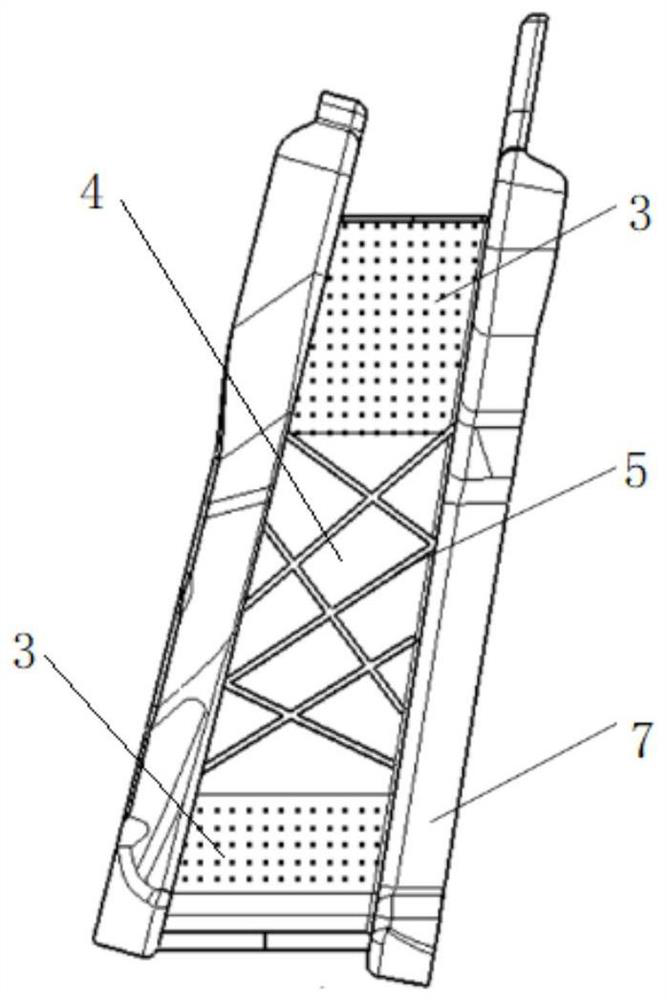
[0029] Foam aluminum materials include foam aluminum plate 2 and foam aluminum block 3 (see image 3 ), the interior of the skeleton 1 is hollow, and the foam...


PUM


Abstract

An integrated C-ring structure comprises a framework and foamed aluminum, the framework is integrally formed by nylon 66 and 50% of a glass fiber material through injection molding, the interior of the framework is hollow, and the foamed aluminum comprises foamed aluminum plates arranged at the corners of the framework and detachably and fixedly connected with the framework and foamed aluminum blocks arranged in the framework in a filling mode. The foamed aluminum blocks are filled in the framework, and the torsional rigidity of the C-ring structure can be increased and the degree of freedom of torsional rigidity adjustment can be improved by replacing the foamed aluminum plates with different foaming rates. The framework further comprises side wall vertical plates which are arranged in abilateral symmetry mode, cavities are formed in the side wall vertical plates, and foamed aluminum blocks and reinforcing ribs are arranged in the cavities to further improve the torsional rigidity ofthe C-ring structure. According to the integrated C-ring structure, a plurality of part welding and riveting structures of an original C-ring structure are replaced, the lightweight requirement is met, and meanwhile the torsional rigidity of the C-ring structure can be improved.

Description

technical field [0001] The invention relates to the field of auto parts, in particular to an integrated C-ring structure. Background technique [0002] The car C-ring structure is a roughly ring-shaped structure formed by connecting the side pillars on both sides of the body, the connecting beams of the left and right side luggage compartments, and the beams on the rear floor. Because it plays a key role in the torsional stiffness of the vehicle, it will It directly affects the handling stability and road noise level of the vehicle when driving, so it is also called "acoustic ring". [0003] The traditional C-ring structure involves many parts and connection points. The current design mostly assembles the parts together by welding or riveting between steel plates, which leads to a more complex overall structure, cumbersome connection process, and requires many Auxiliary stamping dies and welding fixtures cause a waste of human resources and energy; at the same time, the tra...

Claims


Application Information

Patent Timeline
Patent Type & Authority Applications(China)
IPC IPC(8): B62D29/00
CPCB62D29/00B62D29/008
Inventor 宋腾辉林少辉莫静孙震张铭洁李振兴王立
Owner ZHEJIANG GEELY HLDG GRP CO LTD
Why Eureka
Try Eureka