
Unmanned aerial vehicle and cross plate mechanism and control method thereof

A control method and machine cross technology, applied in the aviation field, can solve the problems of large space occupation, complex mechanical structure, and low flight efficiency, and achieve the effect of ensuring control flexibility, simple calculation method, and enhancing flexibility

Active Publication Date: 2021-01-05
尚良仲毅(沈阳)高新科技有限公司
View PDF9 Cites 1 Cited by
  • Summary
  • Abstract
  • Description
  • Claims
  • Application Information

AI Technical Summary

Problems solved by technology

[0002] At present, UAVs with vertical take-off and landing and air hovering capabilities are classified according to the control method, and are mainly divided into two types: helicopters and multi-rotors. The flight efficiency of the latter is low, and it occupies a large space

Method used


Image

  • Unmanned aerial vehicle and cross plate mechanism and control method thereof
  • Unmanned aerial vehicle and cross plate mechanism and control method thereof
  • Unmanned aerial vehicle and cross plate mechanism and control method thereof

Examples


Embodiment Construction

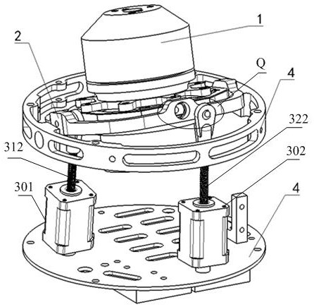
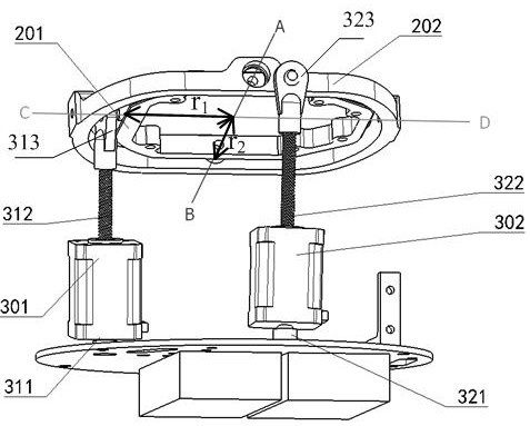
[0063] The invention discloses an unmanned aerial vehicle and its swashplate mechanism and control method, which uses a linear motor to control the angle adjustment of the swashplate, so that the driving process is more simplified and direct, the accuracy is higher, and the calculation method is simpler. And it can guarantee the control flexibility of the UAV.

[0064] The following will clearly and completely describe the technical solutions in the embodiments of the present invention with reference to the accompanying drawings in the embodiments of the present invention. Obviously, the described embodiments are only some of the embodiments of the present invention, not all of them. Based on the embodiments of the present invention, all other embodiments obtained by persons of ordinary skill in the art without making creative efforts belong to the protection scope of the present invention.

[0065] In the UAV control method provided in the embodiment of the present invention,...


PUM


Abstract

The invention relates to the technical field of aviation and discloses an unmanned aerial vehicle and a cross plate mechanism and a control method thereof. In the cross plate mechanism of the unmannedaerial vehicle, an outer ring is hinged to a rack and rotates around a first axis; an inner ring is sleeved with the outer ring and hinged to the outer ring, the inner ring rotates around a second axis, and the second axis is perpendicular to the first axis; in the first linear motor, a first motor body is hinged to the rack, and a first push rod is connected with an inner ring driving connectionpoint on the inner ring; in the second linear motor, a second motor body is hinged to the rack, and a second push rod is connected with an outer ring driving connection point on the outer ring. Whenthe central axis of a power device deflects, a direction angle psi to be reached by the central axis of the power device and an inclination angle [theta]1 of the central axis relative to an initial plane are determined firstly, the [theta]1 is decomposed into [theta]x and [theta]y in the first axis direction and the second axis direction, sin[theta]x is equal to sin[theta]1*cos[psi], and sin [theta]y is equal to sin[theta]1*sin[psi]; [theta]x and [theta]y are converted into travel instructions of the two linear motors. The driving mode is simple and direct, and the precision is high.

Description

technical field [0001] The invention relates to the field of aviation technology, in particular to an unmanned aerial vehicle and its swashplate mechanism and control method. Background technique [0002] At present, UAVs with vertical take-off and landing and air hovering capabilities are classified according to the control method, and are mainly divided into helicopters and multi-rotors. The flying efficiency of the latter is low, and it takes up a lot of space. Contents of the invention [0003] In view of this, the object of the present invention is to provide an unmanned aerial vehicle and its swash plate mechanism and control method, which uses a linear motor to control the angle adjustment of the swash plate, so that the driving process is more simplified and direct, and the accuracy is higher , the calculation method is simpler and can ensure the control flexibility of the UAV. [0004] To achieve the above object, the present invention provides the following tec...

Claims


Application Information

Patent Timeline
Patent Type & Authority Applications(China)
IPC IPC(8): B64C9/00
CPCB64C9/00
Inventor 陈明非姜文辉齐维维英明于海生闫志敏孙昕吕卉甘子东
Owner 尚良仲毅(沈阳)高新科技有限公司
Learn More