
Sludge drying circulation structure and sludge drying system

A technology of sludge drying and recycling structure, applied in the direction of dewatering/drying/concentrating sludge treatment, etc., can solve the problems of high energy consumption and low utilization rate of waste heat, achieve faster efficiency, reasonable and concise arrangement, and solve energy problems. The effect of low consumption

Pending Publication Date: 2021-01-05
浙江远能环保设备有限公司
View PDF0 Cites 2 Cited by
  • Summary
  • Abstract
  • Description
  • Claims
  • Application Information

AI Technical Summary

Problems solved by technology

[0003] In view of this, the present invention aims to propose a sludge drying cycle structure to solve the problems of low waste heat utilization rate and large energy consumption in the low temperature sludge drying process

Method used


Image

  • Sludge drying circulation structure and sludge drying system
  • Sludge drying circulation structure and sludge drying system
  • Sludge drying circulation structure and sludge drying system

Examples


Embodiment Construction

[0039] It should be noted that, in the case of no conflict, the embodiments of the present invention and the features in the embodiments can be combined with each other.

[0040] In describing the present invention, it is to be understood that the terms "upper", "lower", "front", "rear", "left", "right", "vertical", "horizontal", "top" , "bottom", "inner", "outer" and other indicated orientations or positional relationships are based on the orientations or positional relationships shown in the drawings, and are only for the convenience of describing the invention and simplifying the description, rather than indicating or implying Any device or element must have a specific orientation, be constructed and operate in a specific orientation, and therefore should not be construed as limiting the invention. In addition, the terms "first", "second", etc. are used for descriptive purposes only, and should not be understood as indicating or implying relative importance or implicitly sp...


PUM


Abstract

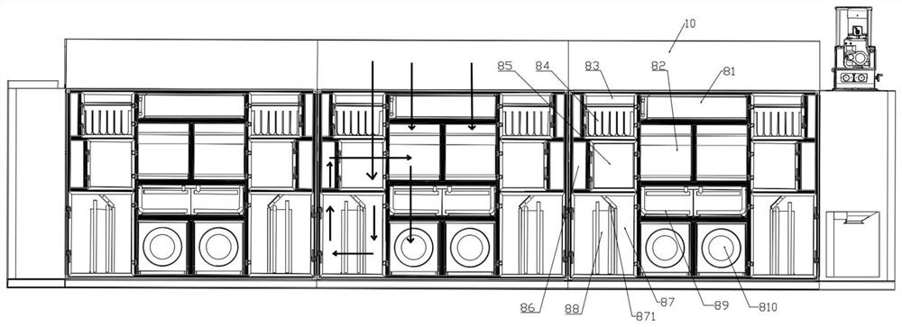
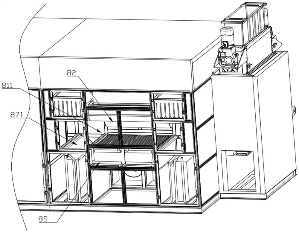
The invention provides a sludge drying circulation structure and a sludge drying system; the sludge drying circulation structure comprises at least two stages of drying heating mechanisms; the first-stage drying heating mechanism introduces damp and hot air generated by drying sludge in a drying chamber, the damp and hot air passes through a first-stage heater, the heated gas is output by a fan topreheat and dry the sludge on an upper-layer crawler belt, and the used gas returns to the first-stage heater to form a circulation process. The second-stage drying heating mechanism make the damp and hot gas produced by sludge in the drying chamber filtered by an air filter and heat-exchanged by a total heat exchanger at the two sides, the filtered and cooled gas is dehumidified through a condenser, the produced dry gas is heated by a second-stage heater after being heated by the total heat exchanger, and the heated gas is output by the fan. The problems that in the low-temperature sludge drying process, the waste heat utilization rate is low, and energy consumption is large are solved.

Description

technical field [0001] The invention belongs to the field of sludge drying, and in particular relates to a sludge drying cycle structure and a sludge drying system. Background technique [0002] The necessary process in sewage treatment is sludge drying and dehydration, and the most environmentally friendly technology among the common sludge drying and dehydration methods is low-temperature sludge drying technology, which uses electric energy to directly heat gas to dry sludge , but the biggest problem in this technology is that there is a lot of waste heat and the recycling rate is relatively low. Contents of the invention [0003] In view of this, the present invention aims to propose a sludge drying cycle structure to solve the problems of low waste heat utilization rate and large energy consumption in the low-temperature sludge drying process. [0004] In order to achieve the above object, the technical solution created by the present invention is achieved in this way...

Claims


Application Information

Patent Timeline
Patent Type & Authority Applications(China)
IPC IPC(8): C02F11/13
CPCC02F11/13
Inventor 陈少军
Owner 浙江远能环保设备有限公司
Learn More