A method for erecting main cables of a suspension bridge with tunnel-type anchorages on both sides

A technology for tunnel-type and suspension bridges, which is applied in the direction of suspension bridges, bridge construction, erection/assembly of bridges, etc. It can solve the problems that the main cable cannot be fully covered, and achieve the effect of simple and reliable setting, convenient operation and simple method

Active Publication Date: 2022-04-15
CCCC SHEC SECOND ENG
View PDF7 Cites 0 Cited by
  • Summary
  • Abstract
  • Description
  • Claims
  • Application Information

AI Technical Summary

Problems solved by technology

[0005] The main cable erection method of the suspension bridge with tunnel anchorage on both sides provided by the present invention aims to overcome the problem that the traditional main cable traction system cannot fully cover the main cable in the prior art for the tunnel anchorage on both banks. Problems in developing a new set of main cable erection methods

Method used


Image

  • A method for erecting main cables of a suspension bridge with tunnel-type anchorages on both sides
  • A method for erecting main cables of a suspension bridge with tunnel-type anchorages on both sides
  • A method for erecting main cables of a suspension bridge with tunnel-type anchorages on both sides

Examples


Embodiment 1

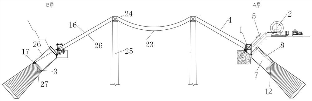
[0039] Such as Figure 1-2 , 7, shown in 10, a kind of suspension bridge main cable erection method of both sides tunnel type anchorage, comprises the following steps:

[0040] 1) Install the cable laying equipment 2 behind the anchorage gantry 1 on bank A, install the main cable traction equipment 4 between the anchorage gantry 1 on bank A and the front anchor surface 3 on bank B, install the main cable traction equipment 4 between the anchorage gantry 1 and Install traction equipment 5 and hoisting equipment 6 between the cable-laying equipment 2, install anchor chamber traction equipment 8 in the anchor room 7 in front of bank A and anchor room 26 in front of bank B, and install traction equipment 8 in the anchor room 7 in front of bank A and in front of bank B Anchor room hoisting equipment 9 is installed in the anchor room 26;

[0041] 2) The anchor head 10 of the main cable is connected to the traction device 5, and the anchor head 10 of the main cable is pulled to the ...

Embodiment 2

[0048] On the basis of Example 1, such as Figure 5-6 As shown, further, the main cable pulling device 4 adopts a circular pulling device, and the working range of the main cable pulling device 4 is that the anchorage gantry 1 on bank A is pulled to the front anchor surface 3 on bank B.

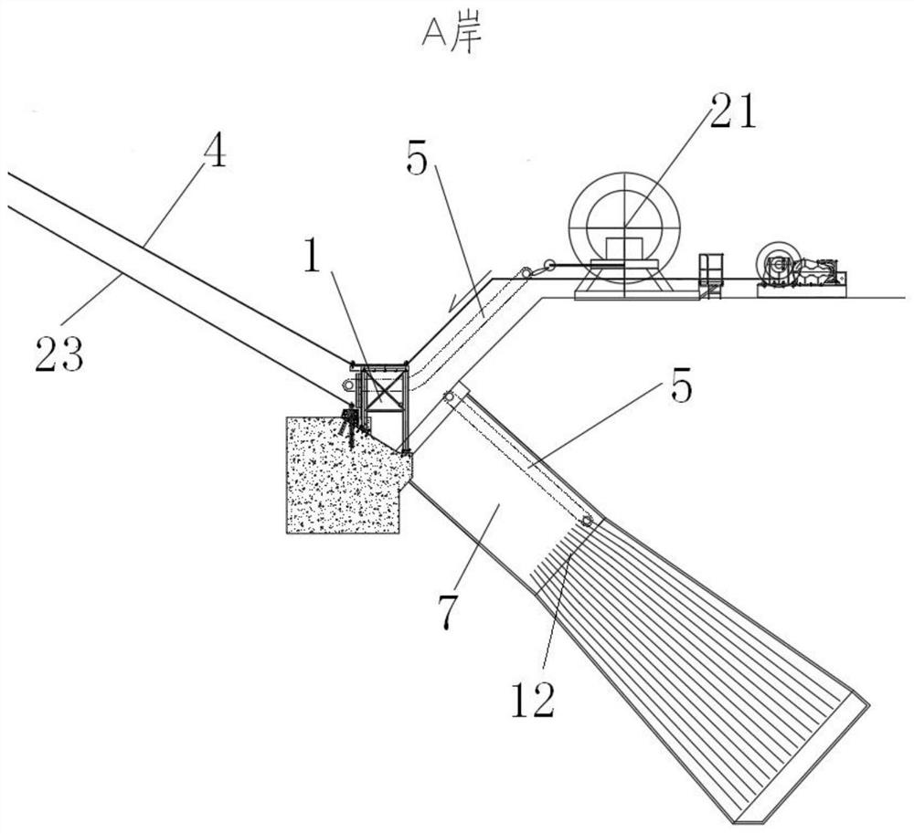
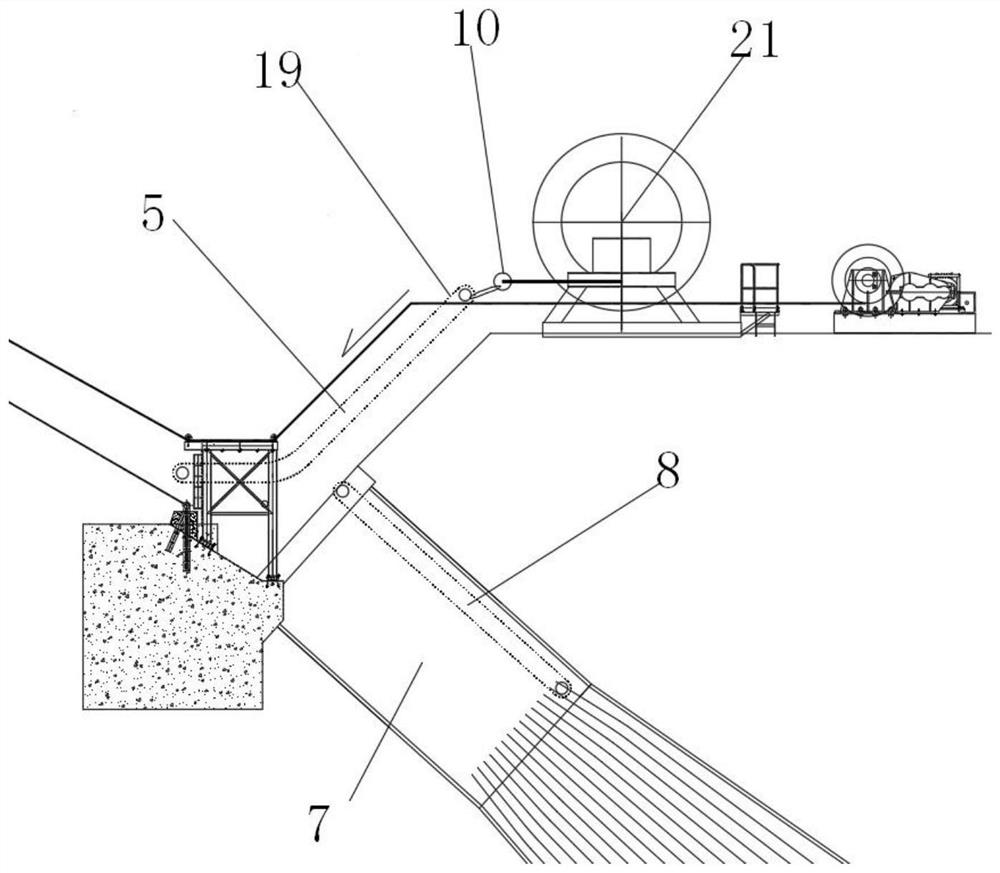
[0049] Such as Figure 3-4 As shown, further, the traction device 5 adopts a circular traction device, and the working range of the traction device 5 is from the cable-laying device 2 to the anchorage gantry 1 on the bank A.

[0050] Such as Figure 8-9 As shown, further, the traction equipment 8 in the anchor chamber adopts circular traction equipment, and the working range of the traction equipment 8 in the anchor chamber is from the anchorage gantry 1 on bank A to the anchor surface 12 in front of bank A.

[0051] Main cable traction equipment 4, traction equipment 5 and anchor chamber traction equipment 8 all adopt circular traction equipment, which has less traction equipment, saves ma...


PUM


Abstract

The invention belongs to the technical field of suspension bridge construction, and in particular relates to a method for erecting a main cable of a suspension bridge with tunnel-type anchorage on both sides, comprising the following steps: the anchor head of the main cable is connected to traction equipment, and the traction equipment pulls it to the anchorage gantry on bank A , the anchor head of the main cable is detached from the traction equipment; the anchor head of the main cable after detachment is pulled from the anchorage gantry of Bank A to the front anchor surface of Bank B by the main cable traction equipment; Equipment: The anchor head at the end of the main cable after being separated is pulled to the main cable anchorage point on the anchor surface in front of A bank by the traction equipment in the anchor room, and the anchor head at the end of the main cable is separated from the traction equipment in the anchor room; The anchor head at the end of the main cable of the indoor traction equipment is connected to the anchor point of the main cable to complete the installation of the main cable; it solves the problem that the traditional main cable traction system in the tunnel anchorage on both sides of the strait cannot fully cover the main cable, and realizes the The full coverage of the main cable in the tunnel anchorage meets the needs of the main cable installation, and the method is simple and easy to operate.

Description

technical field [0001] The invention belongs to the technical field of suspension bridge construction, and in particular relates to a method for erecting main cables of a suspension bridge with tunnel anchorages on both sides. Background technique [0002] Most of the long-span suspension bridges at home and abroad have tunnel-type anchorages on only one bank or gravity anchorages on both banks. Usually, the mature single-wire reciprocating traction system or double-wire reciprocating traction system can be used to complete the erection of the main cable. [0003] In the design of the gravity anchor main cable traction system on both sides of the bank, the steering wheel and the winch are arranged on the back of the anchor on both sides of the bank to achieve full coverage of the main cable. For the design of the main cable traction system of the first-shore tunnel anchor, the winch is installed on the back of the gravity anchor, and the steering wheel is installed on the s...

Claims


Application Information

Patent Timeline
Patent Type & Authority Patents(China)
IPC IPC(8): E01D21/00E01D19/16E01D19/14E01D11/02
CPCE01D21/00E01D19/16E01D19/14E01D11/02
Inventor 丁亚辉张明闪艾国清徐翾玄孙嘉王坤张璐璐柳小胜黄阳林沈冲李欣杨腾王飞月
Owner CCCC SHEC SECOND ENG
Why Eureka
Try Eureka