Dust removal fan

A dust removal fan and air inlet technology, which is applied in the direction of electromechanical devices, mechanical equipment, machines/engines, etc., can solve the problems of eddy air flow, turbulence, and increased power consumption of dust removal fans, so as to reduce power consumption and avoid eddy current or air flow disorder Effect

Pending Publication Date: 2021-01-05
赵万虎
View PDF0 Cites 1 Cited by
  • Summary
  • Abstract
  • Description
  • Claims
  • Application Information

AI Technical Summary

Problems solved by technology

[0003] At present, the dust removal fans all use a motor to drive the centrifugal impeller to rotate to drive the gas flow. The structure of the existing centrifugal impeller includes a front disk, a rear disk and blades, wherein the front disk and the rear disk are arranged at intervals along the airflow direction. They are connected together by blades so that a flow channel is formed between them. When the centrifugal impeller drives the airflow to move, the airflow first moves toward the centrifugal impeller along the axis of the centrifugal impeller and enters the flow channel, while the direction of the airflow entering the flow channel changes. It is perpendicular to the axis of the centrifugal impeller, so that the airflow is prone to vortex or airflow turbulence when changing the direction of movement, resulting in increased power consumption of the dust removal fan

Method used


Image

  • Dust removal fan
  • Dust removal fan
  • Dust removal fan

Examples


Embodiment Construction

[0035] In order to make the purpose, technical solution and advantages of the present invention clearer, the dust removal fan method of the present invention will be further described in detail below in conjunction with the accompanying drawings and embodiments. It should be understood that the specific embodiments described here are only used to explain the present invention, not to limit the present invention.

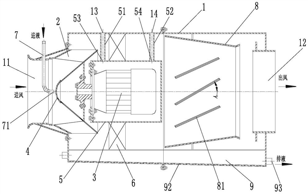
[0036] like figure 1 As shown, a dust removal fan includes: a housing 1, an impeller 2, a motor 3 and a diversion cap 4, the housing 1 is a cylinder, and its axial ends have an air inlet 11 and an air outlet 12 respectively, The motor 3 is fixed inside the casing 1, and the impeller 2 is located inside the casing 1 and is drivingly connected with the motor 3, so that the motor 3 can drive the impeller 2 to rotate, so as to drive airflow into the casing 1 from the air inlet 11, and from Air outlet 12 discharges.

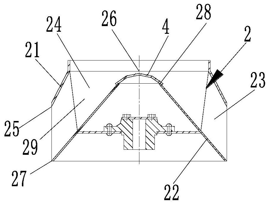
[0037] like figure 2 As shown, the impeller 2 incl...


PUM


Abstract

The invention provides a dust removal fan. The dust removal fan comprises a shell, an impeller, a motor and a flow guide cap. The shell is a cylinder, and an air inlet and an air outlet are formed inthe two axial ends of the shell respectively. The motor is fixed in the shell. The impeller is located in the shell and is in drive connection with the motor. The impeller comprises a front disc, a rear disc and blades. The outer contour of the front disc and the outer contour of the rear disc are each in a circular truncated cone shape, wherein the outer contour of the front disc and the outer contour of the rear disc are gradually shrunk towards the air inlet, and the axis of the front disc and the axis of the rear disc coincide with the axis of the shell. The two axial ends of the front disc and the two axial ends of the rear disc are the large circular end and the small circular end respectively. The outer contour of the flow guide cap is in a spherical segment shape with a central angle less than 180 degrees. The area of the bottom circle of the flow guide cap is greater than that of the small circular end. The bottom circular end of the flow guide cap is fixedly connected to thesmall circular end, the axis of the bottom circular end of the flow guide cap coincides with the axis of the rear disc, and the flow guide cap is gradually shrunk towards the air inlet. According to the dust removal fan, airflow entering the impeller can be guided, the phenomenon of vortexes or airflow turbulence is avoided, and therefore the power consumption of the dust removal fan is reduced.

Description

technical field [0001] The invention relates to the technical field of dust removal, in particular to a dust removal fan. Background technique [0002] A large amount of dust will be generated in the production activities such as industrial production, mining, construction earthwork and tunnel excavation. These dusts will not only endanger human health, but also some combustible dusts may cause explosion. Based on this, the application of dust removal fans has become very extensive. [0003] At present, the dust removal fans all use a motor to drive the centrifugal impeller to rotate to drive the gas flow. The structure of the existing centrifugal impeller includes a front disk, a rear disk and blades, wherein the front disk and the rear disk are arranged at intervals along the airflow direction. They are connected together by blades so that a flow channel is formed between them. When the centrifugal impeller drives the airflow to move, the airflow first moves toward the ce...

Claims


Application Information

Patent Timeline
Patent Type & Authority Applications(China)
IPC IPC(8): F04D25/08F04D29/44F04D29/66F04D29/28F04D29/58F04D29/70F04D29/42H02K5/10H02K5/20B01D50/00
CPCF04D25/08F04D29/441F04D29/667F04D29/281F04D29/5813F04D29/703F04D29/705F04D29/706F04D29/4226H02K5/10H02K5/20B01D50/40
Inventor 赵万虎
Owner 赵万虎
Why Eureka
Try Eureka