The control method of the direction buffer of the oil cylinder of the integral box hopper

A control method and hopper technology, applied in the direction of fluid pressure actuators, sustainable manufacturing/processing, servo motors, etc., can solve problems such as breaking high-voltage power lines, loud working noise, and fast movement of hoppers to avoid damage , slow down the impact of stopping, and avoid the effect of displacement of the compression box

Active Publication Date: 2022-07-12
FUJIAN LONGMA ENVIRONMENTAL SANITATION EQUIP
View PDF5 Cites 0 Cited by
  • Summary
  • Abstract
  • Description
  • Claims
  • Application Information

AI Technical Summary

Problems solved by technology

This working mode: 1. The movement speed of the hopper is fast and the mass of the hopper is large. During the stop of the hopper movement, the acceleration of the hopper is large. The working mode of direct stop will cause a great impact on the hopper during actual working conditions. The mass of the hopper is large, and this impact will cause damage to the structure and the oil cylinder, thereby reducing the service life of the hopper and its oil cylinder, and making a lot of working noise. At present, people have higher and higher requirements for the working environment, so the noise control also put forward higher requirements
2. Due to the different ground conditions of each garbage station, there is often a certain journey when the loading hopper is lowered to the ground, and the speed of the oil cylinder is relatively fast, so it cannot be stopped manually to the exact position, so each loading work The cyclic hopper lowering stroke tends to jack up the hopper and pull it forward a short distance, which may pull the hopper forward a meter or two when it is full
Therefore, for garbage stations with limited space, this problem will be quite prominent, and it is even possible to break the high-voltage power line and cause a safety accident that may cause electric shock to the staff.

Method used


Image

  • The control method of the direction buffer of the oil cylinder of the integral box hopper
  • The control method of the direction buffer of the oil cylinder of the integral box hopper
  • The control method of the direction buffer of the oil cylinder of the integral box hopper

Examples


Embodiment Construction

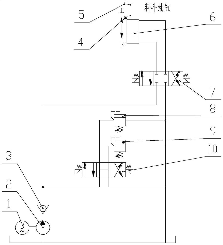
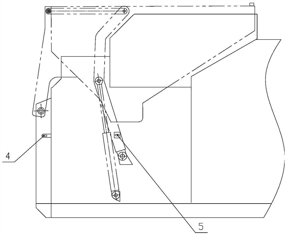
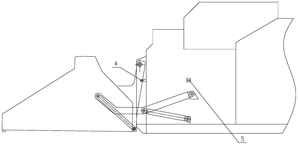
[0019] like Figure 1-3 As shown in one of the present invention, the control method for the direction buffering of the oil cylinder of the overall box hopper, the hydraulic system on which the control method is based includes a hydraulic pump 2 (the hydraulic pump 2 is driven by the motor 1), a three-position four-way electromagnetic reversing valve a7, a hopper The oil cylinder 6, the three-position four-way electromagnetic reversing valve b10, the high-pressure relief valve 8 and the low-pressure relief valve 9, the outlet of the hydraulic pump 2 is connected to the pressure oil port of the three-position four-way electromagnetic reversing valve a7, the said The two outlets of the three-position four-way electromagnetic reversing valve a7 are respectively connected to the large cavity and the small cavity of the hopper cylinder 6 through pipelines, and the oil return port of the three-position four-way electromagnetic reversing valve a7 is connected to the oil tank through p...


PUM


Abstract

The invention discloses a control method for the direction buffering of an oil cylinder of a hopper of an integral box, including the buffering control of the hopper lifting and feeding process and the buffering control of the hopper lowering process; The reversing valve a becomes the right electromagnet to be energized, so that the main pressure oil circuit and the small cavity of the hopper cylinder are connected. The oil inlet of the relief valve is connected, and the driving force is removed when the hopper is lifted and the material needs to be buffered and stopped, and the reverse buffer force is provided; Electricity, unloading in the middle position, removing the driving force of the cylinder for lowering, and relying on the back pressure of the oil return in the large cavity of the hopper cylinder and the buffer pad on the hopper to buffer the deceleration. The invention can effectively slow down the stop impact, so as to greatly avoid the impact on the structure and the oil cylinder, and at the same time generate a large working noise.

Description

technical field [0001] The invention belongs to the field of garbage compression, and particularly relates to a control method for the direction buffering of an oil cylinder of an integral box hopper. Background technique [0002] At present, the hopper feeding stroke of the domestic garbage compression type integrated garbage compression box stops in place and is a direct stop working mode. This working mode: 1. The moving speed of the hopper is fast and the quality of the hopper is large. During the stopping process of the hopper, the acceleration of the hopper is large, and the working method of direct stop will cause a great impact on the hopper in the actual working condition. The mass of the hopper is large, and this impact will cause damage to the structure and the oil cylinder, thereby reducing the service life of the hopper and its oil cylinder, and at the same time, it emits a lot of working noise. At present, people have higher and higher requirements for the work...

Claims


Application Information

Patent Timeline
Patent Type & Authority Patents(China)
IPC IPC(8): F15B11/08F15B15/22F15B15/28B65F3/14
CPCF15B11/08F15B15/22F15B15/2807B65F3/14Y02W90/10
Inventor 贺艺伟张庆明张福燕张宗锋李基锋陈玮烨邓志贵苏森权倪闽睿
Owner FUJIAN LONGMA ENVIRONMENTAL SANITATION EQUIP
Why Eureka
Try Eureka