Supercharge Your Innovation With Domain-Expert AI Agents!

Kitchen air conditioning system

An air-conditioning system and air-conditioning technology, applied in air-conditioning systems, ventilation systems, shielding with air flow, etc., can solve the problems of energy waste, heat removal, heat waste, etc., and achieve the effect of a compact overall structure

Pending Publication Date: 2021-01-05
NINGBO FOTILE KITCHEN WARE CO LTD
View PDF0 Cites 0 Cited by
  • Summary
  • Abstract
  • Description
  • Claims
  • Application Information

AI Technical Summary

Problems solved by technology

[0002] As people pay more and more attention to energy saving and environmental protection, people not only pay attention to the pollution of the environment caused by the exhaust of oil fume, but also begin to pay more and more attention to the problem of heat waste caused by the exhaust of oil fume. However, the current working process of the range hood In the middle, the heat carried by the oil fume exhausted outside is not effectively used before being discharged into the public flue or outdoors, resulting in waste of heat
For example, take the existing kitchen air conditioning system as an example. It is equipped with an air conditioner in the kitchen, and the kitchen air conditioner is used to air condition the kitchen air. Although, in summer, the air outlet of the air conditioner can blow cold air to cool the kitchen air. , the air outlet of the air conditioner can blow out hot air to heat up the kitchen air, thereby improving the user experience. However, the existing kitchen air conditioner is not organically combined with the range hood, and the heat generated by the air conditioner heat exchanger cannot be discharged through the range hood. At the same time, The range hood itself exhausts the fume with heat, which also causes a waste of energy

Method used


Image

  • Kitchen air conditioning system
  • Kitchen air conditioning system

Examples


Embodiment Construction

[0016]The present invention will be described in further detail below in conjunction with the embodiments of the drawings.

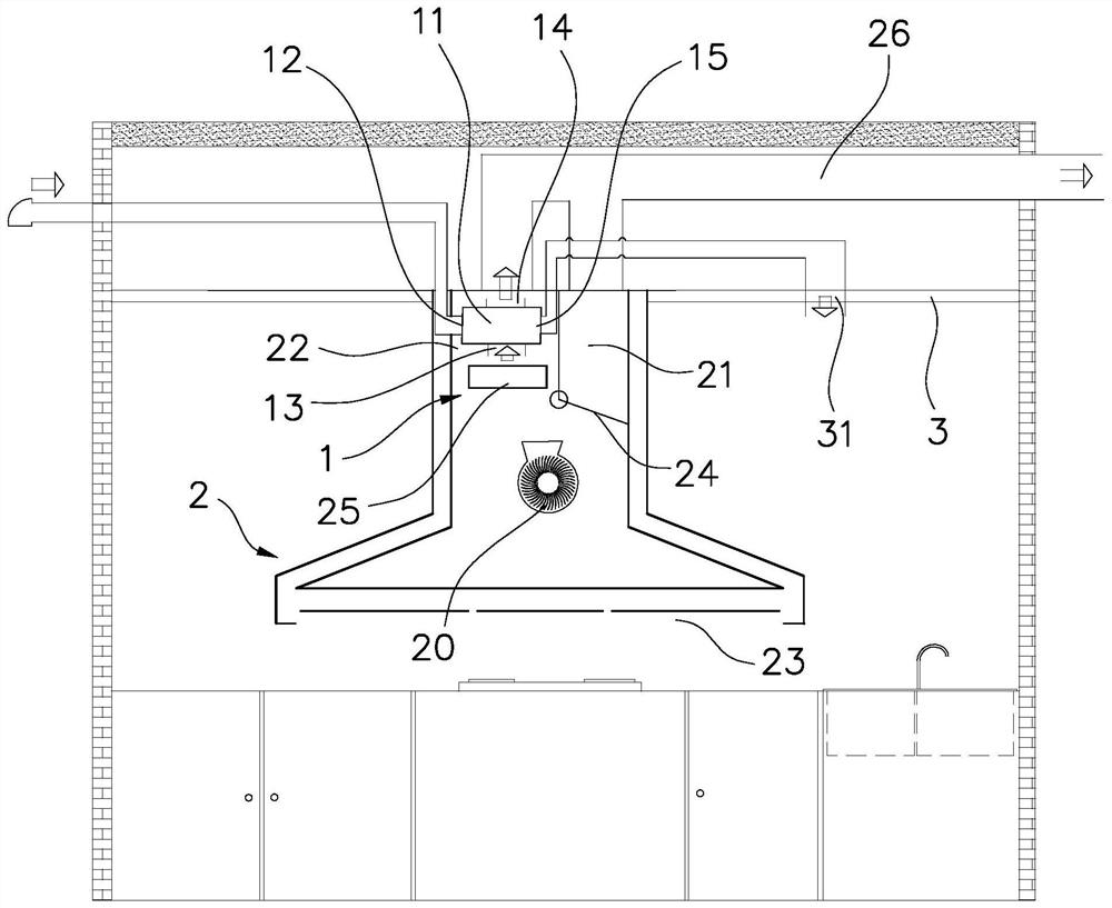
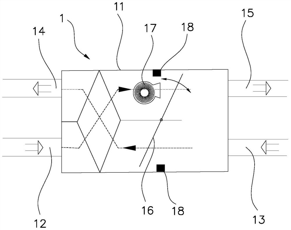
[0017]Such asfigure 1 withfigure 2As shown, the kitchen air conditioning system in this embodiment includes a total heat exchanger 1 and an oil fume suction assembly 2. Among them, the total heat exchanger 1 is integrally integrated on the oil fume suction assembly 2 as an air conditioning assembly. The shell 11 of the total heat exchanger 1 has a first air inlet 12, a second air inlet 13, a first air outlet 14 and a second air outlet 15. The first air inlet 12 communicates with the outdoors, the first air outlet 14 communicates with the outdoors or a public flue, and the second air outlet 15 communicates with the kitchen room through the air supply opening 31 on the kitchen ceiling 3.

[0018]A first air valve 16 for switching wind direction and a fan 17 for providing wind power are installed inside the housing 11, and a block 18 for matching with the first air val...


PUM


Abstract

A kitchen air conditioning system comprises an oil fume suction assembly and a total heat exchanger integrally integrated on the oil fume suction assembly; the total heat exchanger is provided with afirst air inlet, a second air inlet, a first air outlet, a second air outlet and a first air valve; the first air inlet communicates with the outside, the first air outlet communicates with the outside or a public flue, and the second air outlet communicates with the interior of a kitchen; and a first fume exhaust channel of the oil fume suction assembly communicates with the first air outlet, a second fume exhaust channel communicates with the second air inlet, and a second air valve in the oil fume suction assembly is used for switching the fume exhaust channels. According to the kitchen airconditioning system, the total heat exchanger is integrally integrated on a range hood, the overall structure is more compact, the system is controlled to be switched among three different working modes through the air valves, the range hood can be independently used, moreover, air can be supplied to the indoor space after oil fume purification, the purified oil fume can be subjected to heat exchange in the total heat exchanger, and the purpose of supplying heat to the kitchen is achieved.

Description

Technical field[0001]The invention relates to a kitchen air conditioning system.Background technique[0002]As people pay more and more attention to energy conservation and environmental protection, people not only pay attention to the pollution of oil fume efflux, but also pay more and more attention to the problem of heat waste caused by oil fume efflux. However, the current working process of range hoods However, the heat carried by the oil fume discharged outside is not effectively used before being discharged into the public flue or outdoors, resulting in a waste of heat. For example, take the existing kitchen air conditioning system as an example. Air conditioning is installed in the kitchen. The kitchen air conditioning is used to air-condition the kitchen air. Although, in summer, the air outlet of the air conditioner can blow out cold air to cool the kitchen air. , The air-conditioning outlet can blow out hot air to heat up the kitchen air, thereby improving the user experien...

Claims


Application Information

Patent Timeline
Patent Type & Authority Applications(China)
IPC IPC(8): F24F5/00F24F11/65F24F11/72F24F11/89F24F12/00F24F13/02F24F13/20F24F13/30F24C15/20
CPCF24C15/20F24F5/0096F24F12/006F24F13/02F24F13/20F24F13/30F24F2012/008F24F11/65F24F11/72F24F11/89
Inventor 傅海峰曹亚裙余丙松郭俊杰李昂朱启惠赵艳凤崔腾飞
Owner NINGBO FOTILE KITCHEN WARE CO LTD
Features
  • R&D
  • Intellectual Property
  • Life Sciences
  • Materials
  • Tech Scout
  • Unparalleled Data Quality
  • Higher Quality Content
  • 60% Fewer Hallucinations
Learn More