Modeling method for non-stationary characteristics of large-scale antenna array

A large-scale antenna and modeling method technology, applied in the field of communication, can solve problems such as the inability to take into account the evolution of the x-axis and y-axis, the large difference in the situation of scatterer clusters, and the channel measurement results cannot be well corresponded.

Active Publication Date: 2021-01-05
BEIJING UNIV OF POSTS & TELECOMM
View PDF7 Cites 0 Cited by
  • Summary
  • Abstract
  • Description
  • Claims
  • Application Information

AI Technical Summary

Problems solved by technology

Therefore, the final realization of the birth-death process will be affected by occasional extreme situations, which will lead to extreme channel models, making the difference in the scatterer clusters experienced by different antenna elements is too large, as shown in the final simulation results of literature [1]. There are 9 different scatterers clusters between 1 and antenna 32, so that the spatial cross-correlation between antenna elements tends to zero after several wavelengths, which does not correspond well to the channel measurement results
[0009] On the other hand, this method has a high degree of fit with linear arrays and cannot model two-dimensional planar antennas well, such as figure 2 shown
According to the technology of the birth and death process described in the literature [1], the evolution of the x-axis and the y-axis cannot be considered
In literature [2], although the birth-death process in literature [1] is extended to planar antennas by using the method of random center and generating radius according to the birth-death process, it is still based on the assumption that the scatterer cluster will not reappear after disappearing, so it is different from Literature [1] has a similar defect

Method used


Image

  • Modeling method for non-stationary characteristics of large-scale antenna array
  • Modeling method for non-stationary characteristics of large-scale antenna array
  • Modeling method for non-stationary characteristics of large-scale antenna array

Examples


Embodiment Construction

[0070] Exemplary embodiments of the present invention will be described in more detail below with reference to the accompanying drawings. Although exemplary embodiments of the present invention are shown in the drawings, it should be understood that the invention may be embodied in various forms and should not be limited to the embodiments set forth herein. Rather, these embodiments are provided for more thorough understanding of the present invention and to fully convey the scope of the present invention to those skilled in the art.

[0071] Figure 4 is a block diagram of an example computing device 100 arranged to implement a method of modeling non-stationary properties of large-scale antenna arrays in accordance with the present invention. In a basic configuration 102 , computing device 100 typically includes system memory 106 and one or more processors 104 . A memory bus 108 may be used for communication between the processor 104 and the system memory 106 .

[0072] Depe...


PUM


Abstract

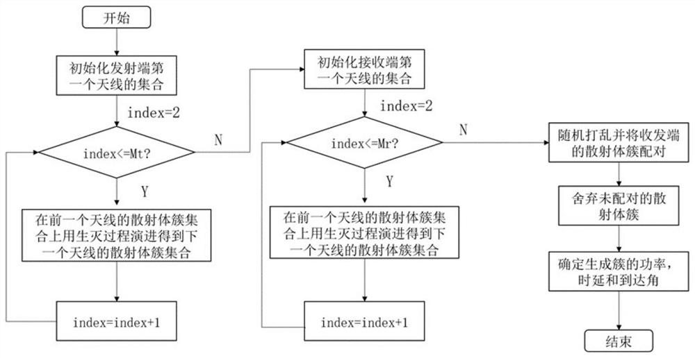
An embodiment of the invention provides a modeling method and device for non-stationary characteristics of a large-scale antenna array and computing equipment; the method is easy to implement, is simple in state transition, can well reflect the dynamic characteristics of a scatterer cluster and is closer to a channel measurement result. Themodeling method comprises the steps: obtaining the dimension information and array element spacing information of a planar antenna, and obtaining the non-stationary characteristics of the planar antenna array; obtaining a first updating rate of the observable scatterer cluster and a second updating rate of the unobservable scatterer cluster; obtaining an observable scatterer cluster set and an unobservable scatterer cluster set of the antenna array elements of the first row and the first column of the planar antenna; calculating the exchange probability of the observable scatterer cluster and the unobservable scatterer cluster according to the arrayelement spacing information and the first updating rate; calculating the replacement probability of the unobservable scatterer cluster according to the array element spacing information and the secondupdating rate; and calculating an observable scatterer cluster set and an unobservable scatterer cluster set of the antenna array elements in any row and any column in the dimension.

Description

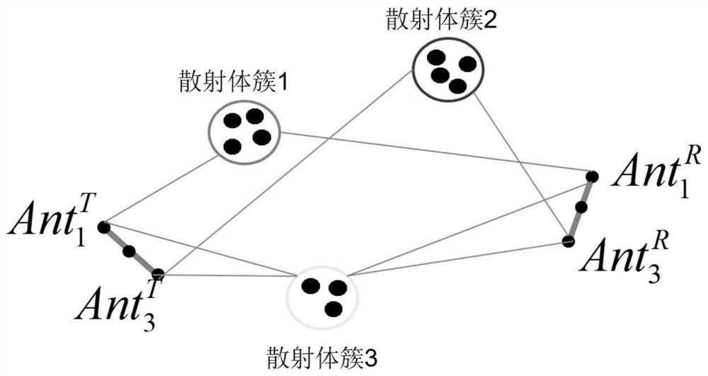
technical field [0001] The invention relates to the field of communication technology, in particular to a modeling method, device and computing equipment for the non-stationary characteristics of a large-scale antenna array. Background technique [0002] In a large-scale antenna array, the number of antenna elements equipped at the transceiver end is large, resulting in an increase in the Rayleigh distance, and the transmission environments experienced by different antenna elements at the transceiver end are different. Non-stationary characteristics, that is, spatial non-stationary characteristics of large-scale antenna arrays. The main manifestations are: the radio waves emitted by different antenna elements at the transmitting end reach the receiving end through different scatterer clusters, such as figure 1 as shown, Arriving via scatterer cluster 1 and scatterer cluster 3 Arriving via scatterer cluster 2 and scatterer cluster 3 in Indicates the i-th antenna elem...

Claims


Application Information

Patent Timeline
IPC IPC(8): H04B17/391H04B7/0413
CPCH04B7/0413H04B17/3912
Inventor 马楠陈诗浩陈建侨许晓东刘宝玲
Owner BEIJING UNIV OF POSTS & TELECOMM
Why Eureka
Try Eureka