
Automatic cup-discharging hot drink machine with selectable tastes

A hot drink machine, automatic technology, applied in the direction of beverage preparation devices, household appliances, applications, etc., can solve the problems of inconvenience, and achieve the effect of balanced proportion and good taste

Inactive Publication Date: 2021-01-08
张红波
View PDF0 Cites 1 Cited by
  • Summary
  • Abstract
  • Description
  • Claims
  • Application Information

AI Technical Summary

Problems solved by technology

[0006] In order to overcome that different hot drink machines can only provide hot drinks of the same taste, when you want to change to other flavors, you need to wash the hot drinks in the hot drink machine before remaking them, or change to another hot drink machine, which is very inconvenient Disadvantages, the technical problem to be solved is: to provide an automatic cup hot drink machine that can add a variety of milk tea powder at the same time, and automatically convey the taste of the paper cup.

Method used


Image

  • Automatic cup-discharging hot drink machine with selectable tastes
  • Automatic cup-discharging hot drink machine with selectable tastes
  • Automatic cup-discharging hot drink machine with selectable tastes

Examples


Embodiment 1

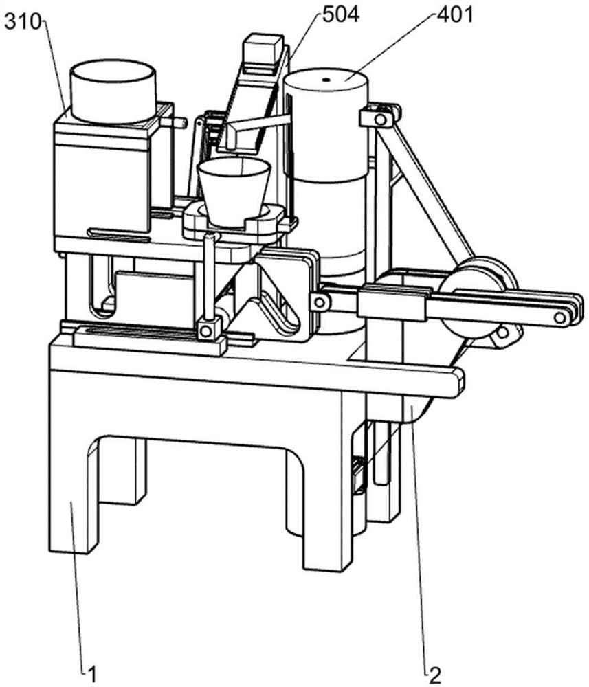
[0093] A kind of automatic cup hot drink machine with optional taste, such as Figure 1-14 As shown, it includes a bracket 1, a power mechanism, a feeding mechanism, a water inlet mechanism and a seasoning mechanism. The bracket 1 is a frame shape with only one upper plate and four legs. Mechanism is fixedly installed on the upper left front side of the support 1, the feeding mechanism is slidably connected with the power mechanism, the water inlet mechanism is fixedly installed on the upper right rear side of the support 1, and the seasoning mechanism is fixedly installed on the upper left rear side of the support 1.

[0094] When people want to have a hot drink, they first put the paper cup into the designated position of the feeding mechanism, put the condiments they want to drink into the designated position of the seasoning mechanism, choose the taste they want to drink, start the power mechanism, and the power mechanism drives the feeding The mechanism moves to send the ...

Embodiment 2

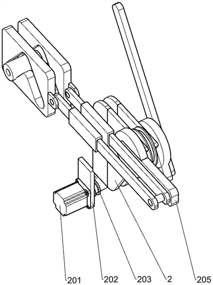
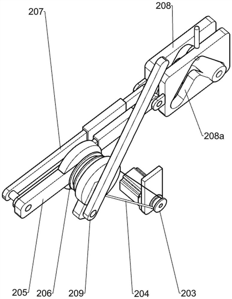
[0096] On the basis of Example 1, such as Figure 2-4 As shown, the power mechanism includes a triangular support plate 2, a motor 201, a first rectangular support plate 202, a driving pulley 203, a turntable 205, a driven pulley 206, a belt 204, a first connecting rod 207, and a first pole 2071 , the first spring 2072, the second connecting rod 2073, the first slide plate 208, the triangular chute 208a and the third connecting rod 209, the two triangular support plates 2 are all fixedly installed on the right side of the plate of the support 1, and the motor 201 is fixedly installed On the rear side of the legs and feet on the right front side of the support 1, the first rectangular support plate 202 is fixedly installed on the lower right side of the support 1 plate, the output shaft of the motor 201 runs through the front and rear sides of the first rectangular support plate 202, and the driving pulley 203 is fixedly installed on the motor. On the output shaft of 201, the d...

Embodiment 3

[0099] On the basis of Example 2, such as Figure 5-7 As shown, the feeding mechanism includes an I-shaped frame 3, a slide rail 301, a U-shaped frame 305, a slider 302, a second pole 303, a sliding column 304, a second slide plate 306, a first fixed block 307, a paddle 308, The third slide plate 309, the support frame 310, the third pole 3101, the fixed column 3102, the second rectangular support plate 3103 and the third rectangular support plate 3104, the middle part of the I-shaped frame 3 is provided with a U-shaped chute, and the I-shaped frame 3 Fixedly installed on the left front side of the upper part of the bracket 1, the two first slide plates 208 are slidingly connected with the I-shaped frame 3, the slide rail 301 is fixedly installed on the bracket 1, the slide rails 301 are located on the front and rear sides of the I-shaped frame 3, and the U-shaped frame The two ends of the lower part of 305 are slidably connected to two slide rails 301 respectively, and the tw...


PUM


Abstract

The invention relates to a hot drink machine, in particular to an automatic cup discharging hot drink machine with selectable tastes. The technical problem to be solved by the invention is to providethe hot drink machine capable of automatically discharging the cups, which can be used for simultaneously adding various milk tea powder and automatically conveying the paper cups and has selectable tastes. According to the technical scheme, the the hot drink machine capable of automatically discharging the cups and with the selectable taste comprises a support, a power mechanism, a feeding mechanism, a water inlet mechanism and a seasoning mechanism; the support is in a frame shape with only one upper plate and four legs, the power mechanism is fixedly installed on the right side of a plate of the support, and the feeding mechanism is fixedly installed on the left front side of the upper portion of the support; the feeding mechanism is slidably connected with the power mechanism, and thewater inlet mechanism is fixedly mounted on the right rear side of the upper portion of the support. The power mechanism is adopted to control the water inlet mechanism and the seasoning mechanism atthe same time, the water inlet amount and the milk tea powder inlet amount within the same time are controlled to a certain extent, and proportional balance is achieved.

Description

technical field [0001] The invention relates to a hot drink machine, in particular to an automatic cup-dispensing hot drink machine with selectable tastes. Background technique [0002] For now, people who want to drink milk tea need to prepare hot water and milk tea powder in advance, manually pour in an appropriate amount of milk tea powder, then slowly pour in hot water, and stir while adding water to make the water and milk tea powder Mix well to complete the hot drink. [0003] When mixing milk tea drinks manually, the ratio of milk tea powder to hot water is not easy to control. When mixing milk tea drinks, first pour an appropriate amount of milk tea powder into a milk tea cup, and then add an appropriate amount of hot water manually. When pouring hot water manually, hot water is easy Splashing scalds people's hands, and also needs to manually stir the two. [0004] Furthermore, in the existing hot drink machines, different hot drink machines can only provide hot dr...

Claims


Application Information

Patent Timeline
Patent Type & Authority Applications(China)
IPC IPC(8): A47J31/00A47J31/40A47J31/44A47J31/46
CPCA47J31/007A47J31/404A47J31/405A47J31/4425A47J31/46A47J31/52
Inventor 张红波
Owner 张红波
Learn More