Calibration method and system for operating tools

A technique of surgical operation and calibration method, applied in the field of robot-assisted surgical systems

Active Publication Date: 2022-02-15
SUZHOU MICROPORT ORTHOBOT CO LTD
View PDF13 Cites 0 Cited by
  • Summary
  • Abstract
  • Description
  • Claims
  • Application Information

AI Technical Summary

Problems solved by technology

[0003] The purpose of the present invention is to provide a calibration method and calibration system for surgical operation tools to solve the problems existing in the contact detection device in the existing robot-assisted surgery system

Method used


Image

  • Calibration method and system for operating tools
  • Calibration method and system for operating tools
  • Calibration method and system for operating tools

Examples


Embodiment 1

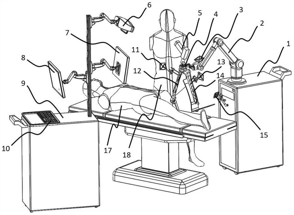
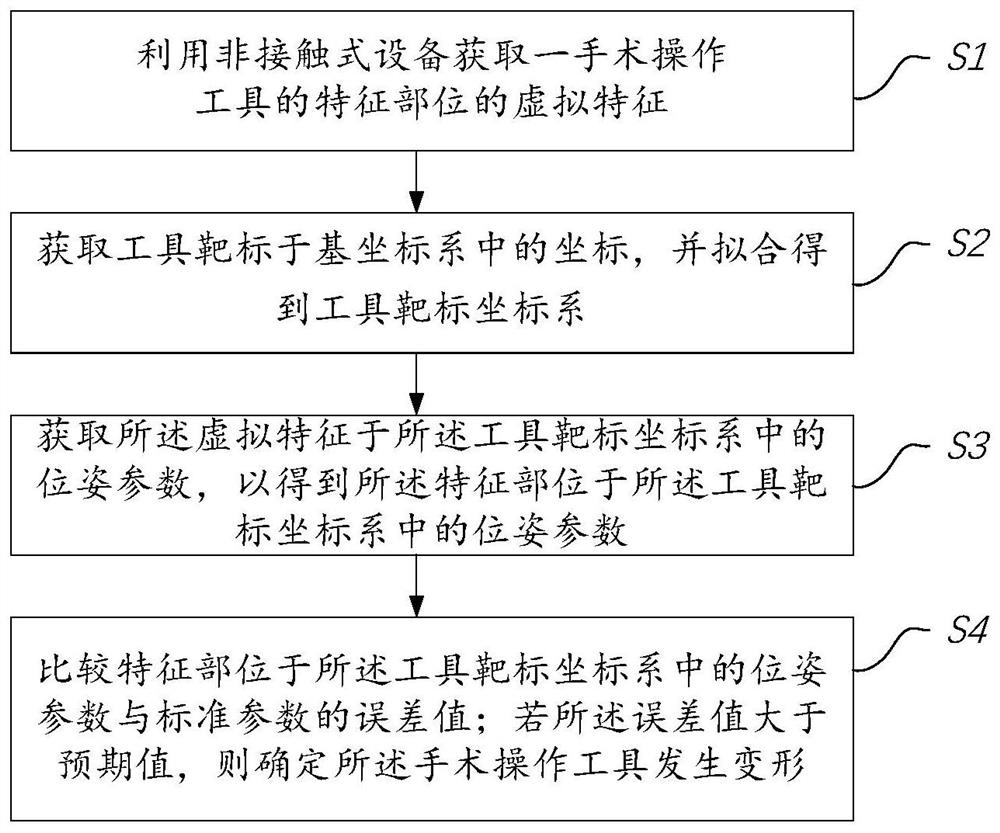
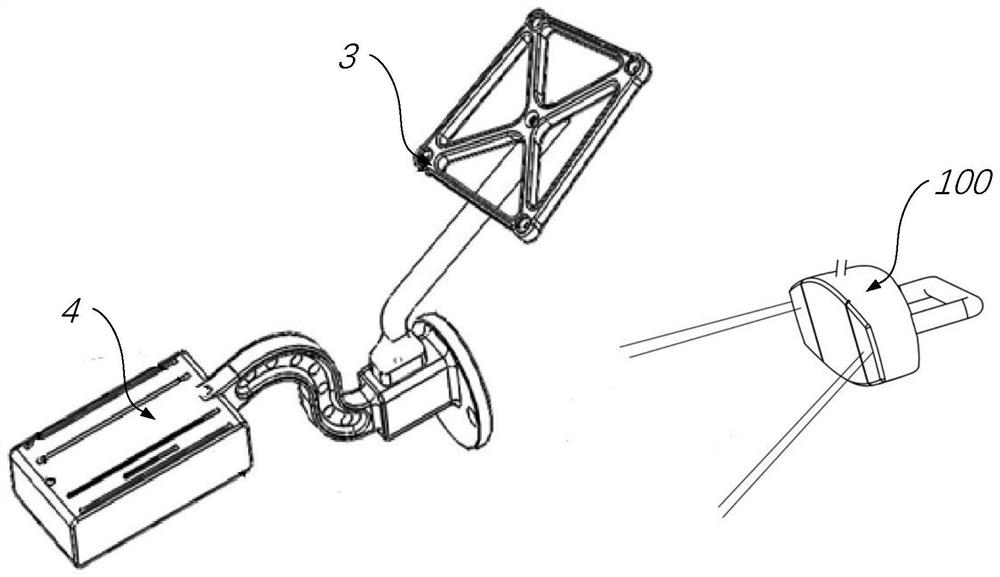
[0060] Please refer to Figure 1 to Figure 4 ,in, figure 1 It is a schematic diagram of performing knee joint replacement using an orthopedic surgery system provided by Embodiment 1 of the present invention; figure 2 It is a flowchart of the verification method provided by Embodiment 1 of the present invention; image 3 It is a schematic diagram of the calibration system of the surgical operation tool provided by Embodiment 1 of the present invention; Figure 4 It is a schematic diagram of the osteotomy guide tool provided by Embodiment 1 of the present invention.

[0061] An embodiment of the present invention provides an orthopedic surgery system, figure 1 What is shown is a schematic diagram of using the orthopedic surgery system to perform knee joint replacement. However, the orthopedic surgery system of the present invention has no special limitation on the application environment, and can also be applied to other orthopedic surgeries. In the following description, a...

Embodiment 2

[0095] Please refer to Figure 5a to Figure 7 ,in, Figure 5a It is a schematic diagram of the transmitting end provided by Embodiment 2 of the present invention; Figure 5b It is a schematic diagram of the receiving end provided by Embodiment 2 of the present invention; Image 6 It is a schematic diagram of the verification system of the surgical operation tool provided by the second embodiment of the present invention, wherein the length of the transmitting end and the receiving end is smaller than the length of the guide groove; Figure 7 It is a schematic diagram of a calibration system for a surgical operation tool provided in Embodiment 2 of the present invention, wherein the length of the transmitting end and the receiving end is not less than the length of the guide groove.

[0096] The verification method and verification system of the surgical operation tool provided by Embodiment 2 of the present invention are basically the same as the verification method and veri...

Embodiment 3

[0108] Please refer to Figure 8 with Figure 9 ,in, Figure 8 It is a schematic diagram of the receiving end provided by Embodiment 3 of the present invention; Figure 9 It is a schematic diagram of the verification system of the surgical operation tool provided by the third embodiment of the present invention.

[0109] The verification method and verification system of the surgical operation tool provided by the third embodiment of the present invention are basically the same as the verification method and verification system of the surgical operation tool provided by the second embodiment, and the same parts will not be described again, and the following only focuses on the differences to describe.

[0110] In this embodiment, the non-contact device includes a through-beam photoelectric module, and the through-beam photoelectric module includes a transmitting end 201 and a receiving end 202, such as Figure 8 with Figure 9 As shown, both the transmitting end 201 and t...


PUM


Abstract

The invention provides a calibration method and a calibration system for a surgical operation tool, which uses a non-contact device to obtain the virtual features of the characteristic parts of a surgical operation tool; obtains the coordinates of the tool target in the base coordinate system, and obtains the tool by fitting Target coordinate system; obtain the pose parameters of the virtual feature in the tool target coordinate system to obtain the pose parameters of the feature part in the tool target coordinate system; compare the feature part in the tool target coordinate system An error value between a pose parameter in the target coordinate system and a standard parameter; if the error value is greater than an expected value, it is determined that the surgical operation tool is deformed. Such a configuration eliminates the steps of disinfection, reduces the risk of infection during the operation, and will not affect the operation process. It will not cause additional wear and tear on surgical operation tools, and has good universality, and can adapt to various surgical operation tools of different shapes, while the non-contact equipment itself does not need to be adjusted.

Description

technical field [0001] The invention relates to the field of robot-assisted surgery systems and methods, in particular to a calibration method and a calibration system for surgical operation tools. Background technique [0002] In artificial joint replacement surgery, it is necessary to use various positioners, guides, etc., for osteotomy before artificial joint installation, so as to ensure the accuracy of osteotomy operation. Different approaches have been proposed to assist surgeons in the positioning of osteotomy guide tools during total knee arthroplasty (TKA) surgery. Generally, in the existing robot-assisted surgery system, an osteotomy guide tool is provided at the end of the robotic arm, and the movement of the osteotomy guide tool is controlled by the robotic arm to realize the positioning of the osteotomy guide tool during knee joint replacement surgery. During the registration of the robotic arm, both the robotic arm system and the positioning system need to obt...

Claims


Application Information

Patent Timeline
Patent Type & Authority Patents(China)
IPC IPC(8): A61B34/20A61B34/10A61B34/30A61B34/00A61B17/15
CPCA61B34/20A61B34/10A61B34/30A61B34/70A61B17/154A61B17/155A61B17/157A61B2034/102A61B2034/2068A61B2034/2055A61B2034/108
Inventor 孙腾马菁阳宋雪迎邵辉何超刘鹏飞
Owner SUZHOU MICROPORT ORTHOBOT CO LTD
Why Eureka
Try Eureka