Pressure-reducing atomization spray valve for carbon dioxide propellant paint spraying

A carbon dioxide and propellant technology, applied in the direction of injection device, liquid injection device, etc., can solve the problems of inability to achieve atomization effect, poor compatibility of primers, flammable and explosive, etc., and achieve good decompression effect and increase Friction, the effect of improving stability

Pending Publication Date: 2021-01-08
湖北金贝壳科技有限公司
View PDF0 Cites 2 Cited by
  • Summary
  • Abstract
  • Description
  • Claims
  • Application Information

AI Technical Summary

Problems solved by technology

The disadvantage is that the two gases are flammable and explosive, so aerosol cans have been under control and are inconvenient to carry
[0003] At present, carbon dioxide gas is gradually used as the pressurized gas to replace the above two gases, but carbon dioxide is an inert gas, which has poor compatibility with the base material, so it needs to be filled to a higher pressure (about 4Mpa) to ensure sufficient The gas is used as the propellant gas until the bottom material in the tank is sprayed, and the high air pressure will cause the sprayed bottom material to be not in the form of mist, but in the form of a linear liquid column, which cannot achieve the atomization effect required for spray paint spraying, so Urgent need to design a pressure reducing atomizing spray valve for carbon dioxide propellant painting

Method used


Image

  • Pressure-reducing atomization spray valve for carbon dioxide propellant paint spraying
  • Pressure-reducing atomization spray valve for carbon dioxide propellant paint spraying
  • Pressure-reducing atomization spray valve for carbon dioxide propellant paint spraying

Examples


Embodiment Construction

[0020] The following will clearly and completely describe the technical solutions in the embodiments of the present invention with reference to the accompanying drawings in the embodiments of the present invention. Obviously, the described embodiments are only some, not all, embodiments of the present invention. Based on the embodiments of the present invention, all other embodiments obtained by persons of ordinary skill in the art without making creative efforts belong to the protection scope of the present invention.

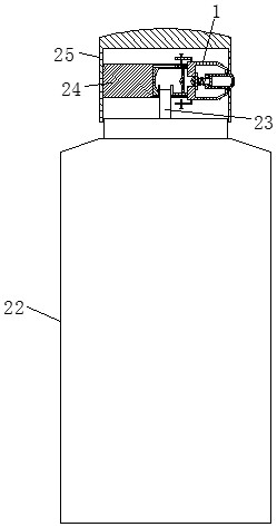
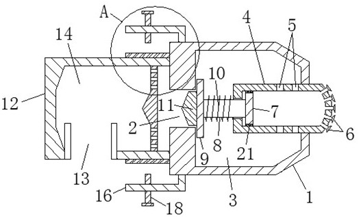
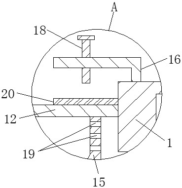
[0021] see Figure 1-4 , the present invention provides a kind of technical scheme: the decompression atomization spray valve of carbon dioxide propellant spraying paint, comprises paint spray tank 22, and on the paint spray tank 22 is equipped with feed pipe 23, and the top of paint spray tank 22 is provided with valve cover 25, and valve cover The inner wall of 25 is fixedly connected with a connecting pipe 24, a valve body 1 is arranged in the connecting pi...


PUM


Abstract

The invention discloses a pressure-reducing atomization spray valve for carbon dioxide propellant paint spraying. The pressure-reducing atomization spray valve comprises a paint spraying tank; a material guiding pipe is installed on the paint spraying tank; a valve deck is arranged at the top of the paint spraying tank; the inner wall of the valve deck is fixedly connected with a connecting pipe;a valve body is arranged in the connecting pipe; a pressure-reducing opening is formed in the surface of the valve body, a material spraying cavity is formed in the valve body, and a material sprayingbin is arranged in the material sprayingcavity; a piston is arranged in the material spraying bin, a pressure-reducing rod is fixedly connected to the piston, the other end of the pressure-reducing rod penetrates through the material spraying bin and is fixedly connected with a limiting block, and a spring is wound around a rod body of the pressure-reducing rod; the limiting block is fixedly connected with a pressure-reducing block; and one side of the valve body is fixedly connected with a pressure-reducing bin, a feeding port is formed in the bottom of the pressure-reducing bin, a pressure-reducing cavity is formed in the pressure-reducing bin, and the inner wall of the pressure-reducing cavity is fixedly connected with a pressure-reducing plate. The pressure-reducing atomization sprayvalve has the characteristics of being reasonable in structural design, convenient to use, high in stability, not prone to falling off, capable of effectively reducing the air pressure of propelling gas and enabling sprayed paint to be in a mist shape and the like.

Description

technical field [0001] The invention relates to the technical field of atomizing spray valves, in particular to a pressure-reducing atomizing spray valve for carbon dioxide propellant painting. Background technique [0002] Existing aerosol can spray paint, or not limited to spray paint, any aerosol can is inflated and pressurized as the propellant gas for injection, usually propane butane or dimethyl ether is used as the pressurized gas, because these two gases are compatible with the primer It has good solubility and can be dissolved in the base material after pressurization. When it needs to be used, it can escape when shaken to form a pressurized effect (refer to the effect of shaking Coke). The disadvantage is that the two gases are flammable and explosive, so aerosol cans have been under control and are inconvenient to carry. [0003] At present, carbon dioxide gas is gradually used as the pressurized gas to replace the above two gases, but carbon dioxide is an inert ...

Claims


Application Information

Patent Timeline
Patent Type & Authority Applications(China)
IPC IPC(8): B05B9/04B05B12/00
CPCB05B9/04B05B12/002
Inventor 孔少补张莉薇孔维雍孔维伟
Owner 湖北金贝壳科技有限公司
Why Eureka
Try Eureka