Welding robot moving mechanism

A welding robot and mobile mechanism technology, applied in welding equipment, auxiliary welding equipment, welding/cutting auxiliary equipment, etc., can solve the problems of unfavorable flange and web welding, troublesome movement of welding robots, inconvenient handling of equipment, etc., and achieve improvement Structural strength and overall firmness, ensuring coherence and stability, and improving the effect of moving stability and safety

Inactive Publication Date: 2021-01-08
ZHEJIANG CONSTR ENG GRP CO LTD
View PDF6 Cites 0 Cited by
  • Summary
  • Abstract
  • Description
  • Claims
  • Application Information

AI Technical Summary

Problems solved by technology

[0003] The flange and web of H-shaped steel are realized by welding. The existing welding robot is heavy and is often lifted by other equipment during transportation. However, it is not convenient for the transportation equipment to enter the workshop with a small space. Therefore, welding It is very troublesome when the robot moves. It is time-consuming and labor-intensive to carry the robot, and there is a hidden danger of tipping. It is also not conducive to the welding between the wing plate and the web plate. The production efficiency is not high, and it can no longer meet the existing needs.

Method used


Image

  • Welding robot moving mechanism
  • Welding robot moving mechanism
  • Welding robot moving mechanism

Examples


Embodiment

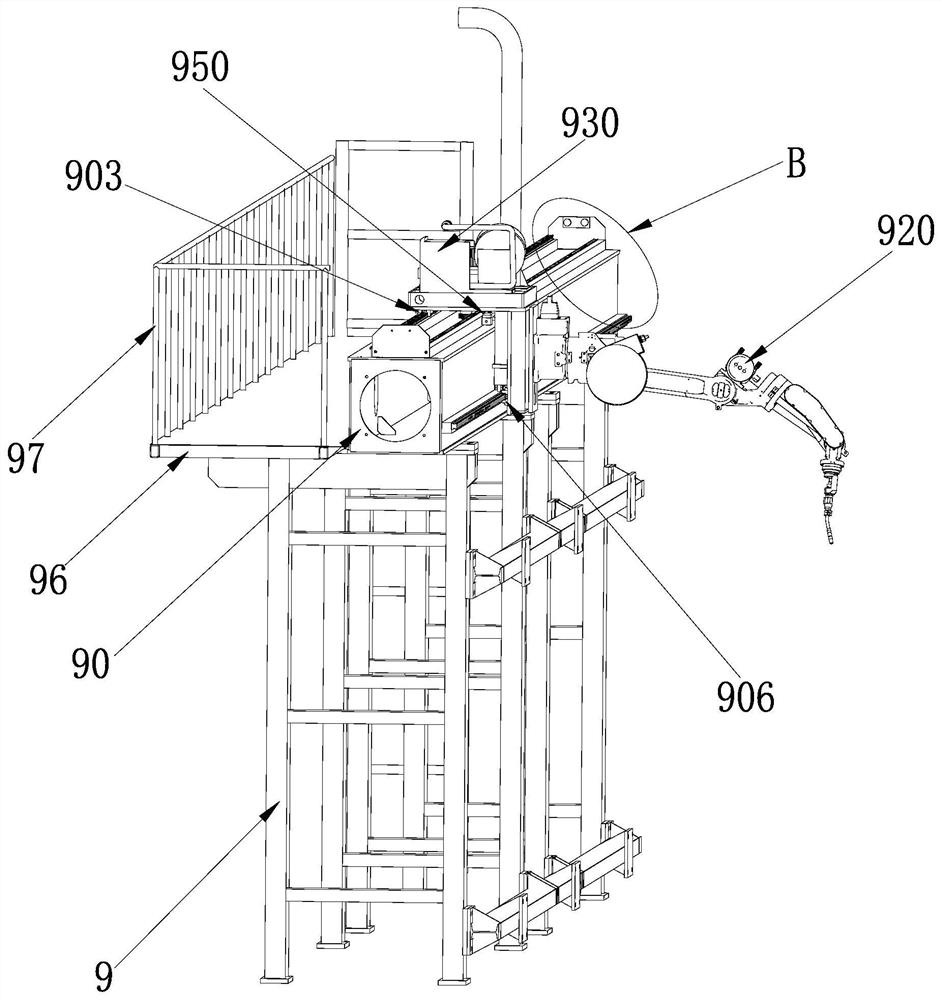
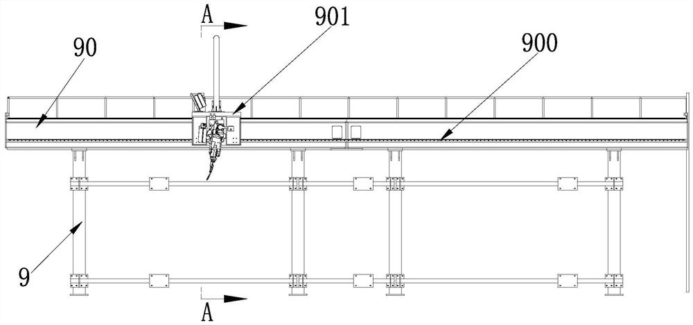
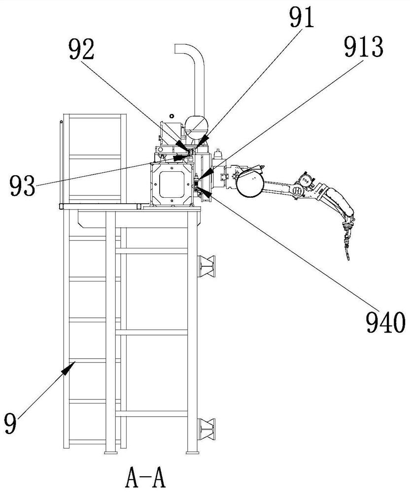
[0034] Example: such as Figure 1-5 As shown, a welding robot moving mechanism includes a support frame 9, a beam 90 is fixed on the support frame 9, and a sliding mechanism 900 is arranged along the length direction of the beam 90; a robot support seat 910 slidably assembled on the sliding mechanism 900, The welding robot 920 is assembled on the robot supporting base 910, and the welding machine moving mechanism 930 is arranged on the robot supporting base 910. The welding machine moving mechanism 930 can drive the welding robot 910 to translate along the sliding mechanism 900; The welding machine moving mechanism is set, and the welding robot translates along the sliding mechanism; the moving stability and safety of the welding robot are improved, and the welding robot is very convenient to move.

[0035] The robot support base 910 has an "L"-shaped structure, including a transverse plate 911 and a longitudinal plate 912; the transverse plate 911 and the longitudinal plate 9...


PUM


Abstract

The invention relates to a welding robot moving mechanism which comprises a supporting frame. A cross beam is fixedly arranged on the supporting frame, and a sliding mechanism is arranged in the length direction of the cross beam. A robot supporting base is assembled on the sliding mechanism in a sliding mode, a welding robot is assembled on the robot supporting base, a welding machine moving mechanism is arranged on the robot supporting base, and the welding machine moving mechanism can drive the welding robot to horizontally move along the sliding mechanism. The welding robot moving mechanism is simple in structure and ingenious in design, and by arranging the welding machine moving mechanism, the welding robot horizontally moves along the sliding mechanism; and the moving stability andsafety of the welding robot are improved, and the welding robot is quite convenient to move.

Description

technical field [0001] The invention belongs to the technical field of steel plate processing, and in particular relates to a moving mechanism of a welding robot. Background technique [0002] H-shaped steel is an economical cross-section high-efficiency profile with more optimized cross-sectional area distribution and a more reasonable strength-to-weight ratio. It is named because its cross-section is the same as the English letter "H". H-shaped steel is assembled from two flanges and one web, and the relative positional relationship between the web and the flange directly affects the pass rate of the finished H-shaped steel. [0003] The flange and web of H-shaped steel are realized by welding. The existing welding robot is heavy and is often lifted by other equipment during transportation. However, it is not convenient for the transportation equipment to enter the workshop with a small space. Therefore, welding It is very troublesome to move the robot. It is time-consumi...

Claims


Application Information

Patent Timeline
Patent Type & Authority Applications(China)
IPC IPC(8): B23K37/02
CPCB23K37/0211
Inventor 金睿胡强尤可坚邱甜何祉健丁宏亮李毅张少君蒋燕芳陈思远邹俊吴绪初
Owner ZHEJIANG CONSTR ENG GRP CO LTD
Why Eureka
Try Eureka