
Kingpin unit

A main shaft, hollow technology, applied in the direction of bearing components, shafts, bearings, etc., can solve complex problems

Pending Publication Date: 2021-01-08
AB SKF
View PDF0 Cites 0 Cited by
  • Summary
  • Abstract
  • Description
  • Claims
  • Application Information

AI Technical Summary

Problems solved by technology

However, due to the rotation of the bearing housing (the housing in which the bearings reside), positioning the sensor on the rotating bearing housing and transmitting the signal to a stationary part (such as a stationary pod housing) is complicated

Method used


Image

  • Kingpin unit
  • Kingpin unit
  • Kingpin unit

Examples


Embodiment Construction

[0041] In the following, identical or functionally equivalent components are assigned the same reference symbols.

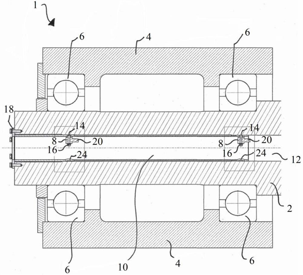
[0042] figure 1 A sectional view of the central spindle unit 1 in the length direction is shown. In this case, as a demonstration, this is the central main shaft unit 1 of a tidal turbine. However, the central spindle unit 1 described here can also be used in other fields such as wheel bearings of motor vehicles, planetary gearboxes or wind turbines. The central spindle unit 1 comprises a central spindle 2 supported by bearings 6 in a housing 4 . In order to be able to monitor the state of the bearing 6 , a sensor 8 is provided. These sensors 8 may, for example, be vibration sensors.

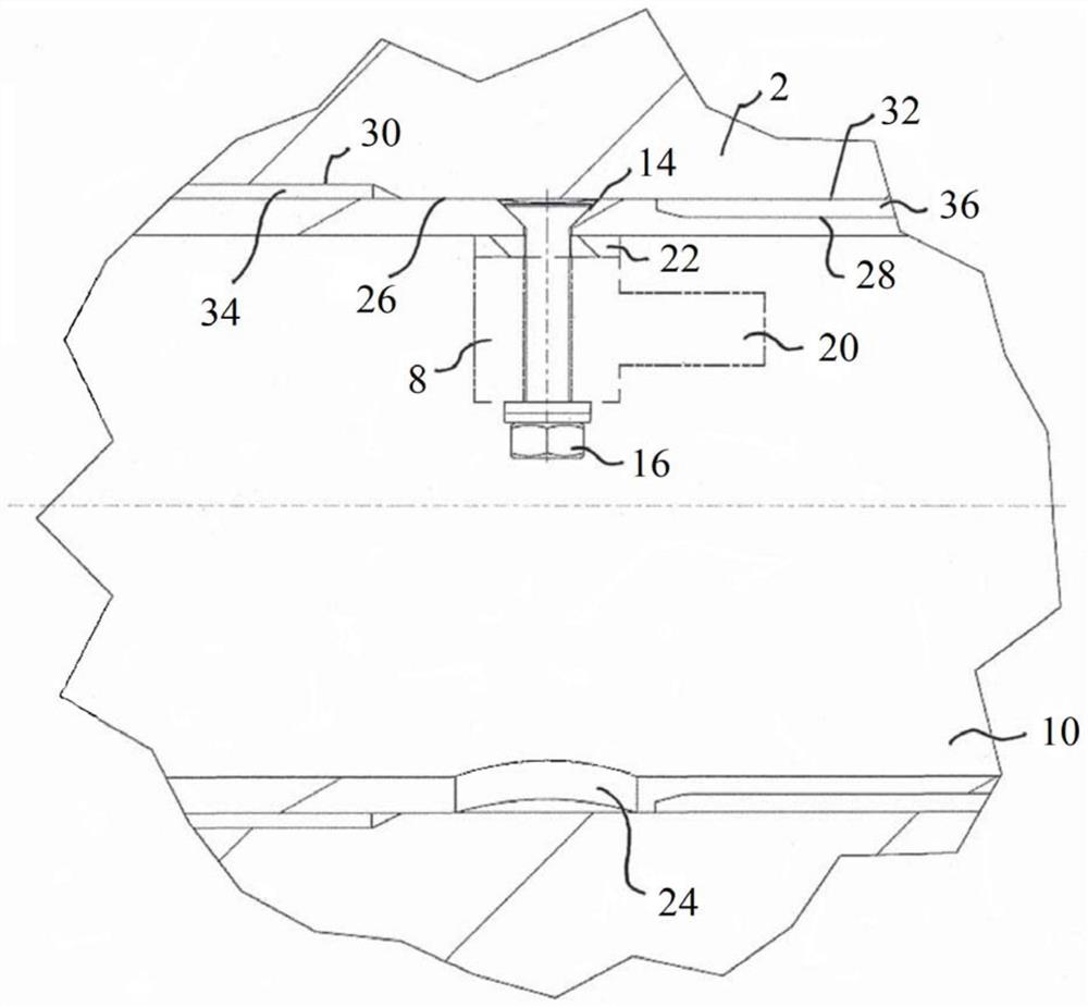
[0043] In order to be able to position the sensor 8 as close as possible to the bearing 6 , a sensor tube 10 is provided which is arranged in the bore 12 of the central spindle 2 . Here, the sensor 8 is arranged in the sensor tube 10 in order to position it as close as possibl...


PUM


Abstract

Disclosed is a kingpin unit (1) including a kingpin (2) that includes an inner bore (12), wherein the kingpin unit (1) includes a sensor tube (10) that is configured as a hollow sleeve and is disposedin the inner bore (12) of the kingpin (2), wherein at least one sensor (8) is disposed in the sensor tube (10), which sensor (8) is configured to monitor at least one bearing (6) of the kingpin (2).

Description

technical field [0001] The present invention relates to the central spindle unit described in the preamble of technical solution 1, which includes a stationary central spindle. Background technique [0002] Directly driven tidal turbines, which include slow-moving ring generators, can be applied in the field of marine energy. Here, a stationary central spindle (kingpin or KingPin) may be supported in a rotating housing. Such stationary central spindles can also be used in other fields such as wheel bearings of motor vehicles, planetary transmissions or wind turbines. The support is usually realized by one or more than one bearing (rolling bearing or sliding bearing). In order to ensure the correct functioning of bearings and rotating bearing units, it is necessary to monitor the bearings used so that bearing failures can be detected in time so that corresponding reactions can be made. For example, vibration sensors can be used to detect non-ideal vibrations of bearings th...

Claims


Application Information

Patent Timeline
IPC IPC(8): F16C35/12F16C19/52
CPCF16C35/12F16C19/527F16C19/52F16C19/525F16C2360/00F16C41/007F16C2233/00F16C19/54G01M13/045B60B27/0005B60G2204/115F03D17/00F03D80/70F16C19/04F16H3/44F16C19/08
Inventor 迈克尔·鲍曼马蒂亚斯·霍夫曼
Owner AB SKF
Learn More