Magnetic liquid damping shock absorber based on first-order and second-order buoyancy principles

A magnetic liquid, second-order buoyancy technology, used in shock absorbers, friction shock absorbers, shock absorbers, etc., can solve the problems of slow movement of permanent magnets, radial disturbances, easy collision with shell walls, etc., to improve efficiency and Vibration reduction effect, excellent vibration reduction effect, flexible movement effect

Active Publication Date: 2021-01-08
TSINGHUA UNIV
View PDF9 Cites 6 Cited by
  • Summary
  • Abstract
  • Description
  • Claims
  • Application Information

AI Technical Summary

Problems solved by technology

[0003] However, the magnetic liquid damping shock absorber in the related art cannot be applied in engineering practice due to various structural problems
For example, in CN102032304A, a cylindrical permanent magnet is used as a damping mass, and the second-order buoyancy principle of the magnetic liquid is used to suspend the permanent magnet in the housing. Since the magnetic liquid is filled with the housing, the movement of the permanent magnet is very slow. The flow between the magnet and the housing is also very difficult, resulting in poor damping of the shock absorber
Another example is CN104895983A, which adopts the first-order buoyancy principle of magnetic liquid to suspend the non-magnetic mass block in the shell, but since the mass block is not effectively constrained in the radial direction, it is prone to radial disturbance, which causes the mass block to easily occur when it is vibrated. Inclined, prone to colliding with shell walls, and still impractical because the shell is filled with magnetic fluid and the motion of the mass is limited

Method used


Image

  • Magnetic liquid damping shock absorber based on first-order and second-order buoyancy principles
  • Magnetic liquid damping shock absorber based on first-order and second-order buoyancy principles
  • Magnetic liquid damping shock absorber based on first-order and second-order buoyancy principles

Examples


Embodiment Construction

[0026] Embodiments of the invention are described in detail below, examples of which are illustrated in the accompanying drawings. The embodiments described below by referring to the figures are exemplary and are intended to explain the present invention and should not be construed as limiting the present invention.

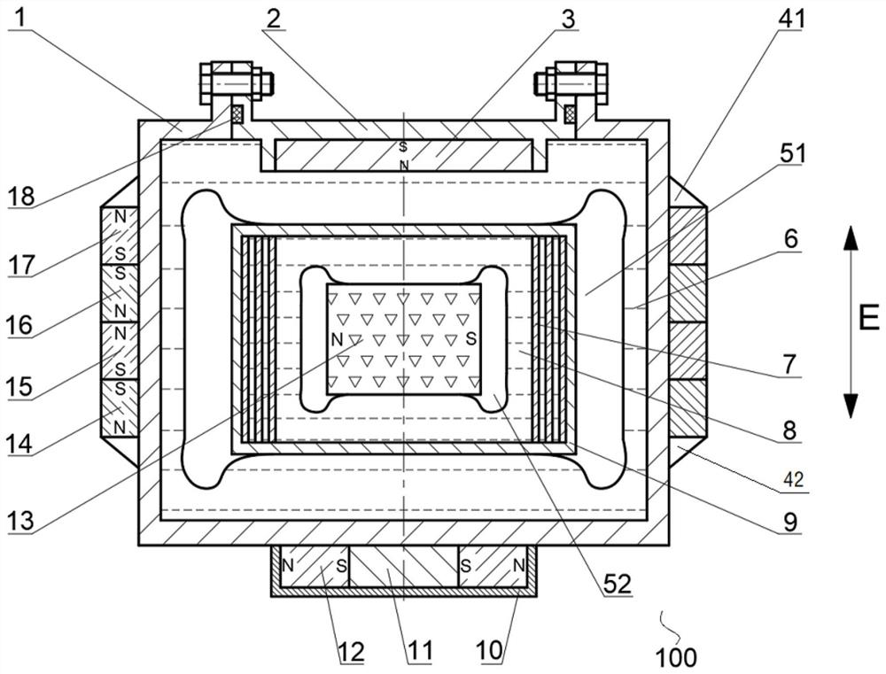
[0027] Refer below Figure 1 to Figure 4 The magnetic liquid damping shock absorber 100 based on the first-order and second-order buoyancy principles according to an embodiment of the present invention will be described.

[0028] Such as figure 1 As shown, the magnetic liquid damping shock absorber 100 according to the embodiment of the present invention includes a housing, a first permanent magnet 3, a second permanent magnet 12, a non-magnetic shell 9, a suspension permanent magnet 13, a first magnetic liquid 6 and a second permanent magnet. Two magnetic liquids8.

[0029] The housing defines a first closed cavity. Both the first permanent magnet 3 and the ...


PUM


Abstract

The invention provides a magnetic liquid damping shock absorber based on first-order and second-order buoyancy principles. The magnetic liquid damping shock absorber comprises a shell, a first permanent magnet, a second permanent magnet, a non-magnetic shell, a suspension permanent magnet, first magnetic liquid and second magnetic liquid. A first closed cavity is defined by the shell. The first permanent magnet and the second permanent magnet are both arranged on the shell. The non-magnetic shell is located in the first closed cavity; a second closed cavity is defined by the non-magnetic shell; and a first magnetic liquid cavity is defined between the non-magnetic shell and the shell. The suspension permanent magnet is located in the second closed cavity; and a second magnetic liquid cavity is defined between the suspension permanent magnet and the non-magnetic shell. A part of the first magnetic liquid cavity is filled with the first magnetic liquid; and a part of the second magneticliquid cavity is filled with the second magnetic liquid. The magnetic liquid damping shock absorber provided by the embodiment of the invention has the beneficial effects of being excellent in shock absorption effect and more sensitive in response to small-amplitude and low-frequency vibration.

Description

technical field [0001] The invention relates to the field of mechanical engineering vibration control, in particular to a magnetic liquid damping shock absorber based on first-order and second-order buoyancy principles. Background technique [0002] Magnetic fluid is a new type of functional material with fluidity and magnetism, and its unique properties make it widely used in engineering fields. The magnetic liquid damping shock absorber is a passive shock absorber with high sensitivity to inertial force, and has the advantages of simple structure, small size, large energy consumption and long life. Therefore, the magnetic liquid damping shock absorber is widely used in the low-frequency, small-amplitude vibration reduction of long straight objects of large spacecraft (such as solar panels and antennas of space stations, etc.). At the same time, it also has broad application prospects on the ground, such as vibration reduction of high-power antennas up to 100 meters long, ...

Claims


Application Information

Patent Timeline
Patent Type & Authority Applications(China)
IPC IPC(8): F16F6/00F16F7/08
CPCF16F6/00F16F7/082F16F2222/04F16F2222/06F16F2222/12
Inventor 李德才韩鹏栋李倩李英松任思杰
Owner TSINGHUA UNIV
Why Eureka
Try Eureka