Anti-leakage structure of gas pipe
A technology of anti-leakage and gas pipes, applied in pipeline systems, gas/liquid distribution and storage, electromagnetic audible signals, etc., can solve the problems of potential safety hazards, no active anti-leakage of gas pipelines, and difficult gas discharge into the atmosphere, etc., to achieve protection The effect of normal operation
- Summary
- Abstract
- Description
- Claims
- Application Information
AI Technical Summary
Problems solved by technology
Method used
Image

Examples
Embodiment 1
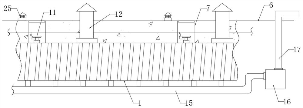
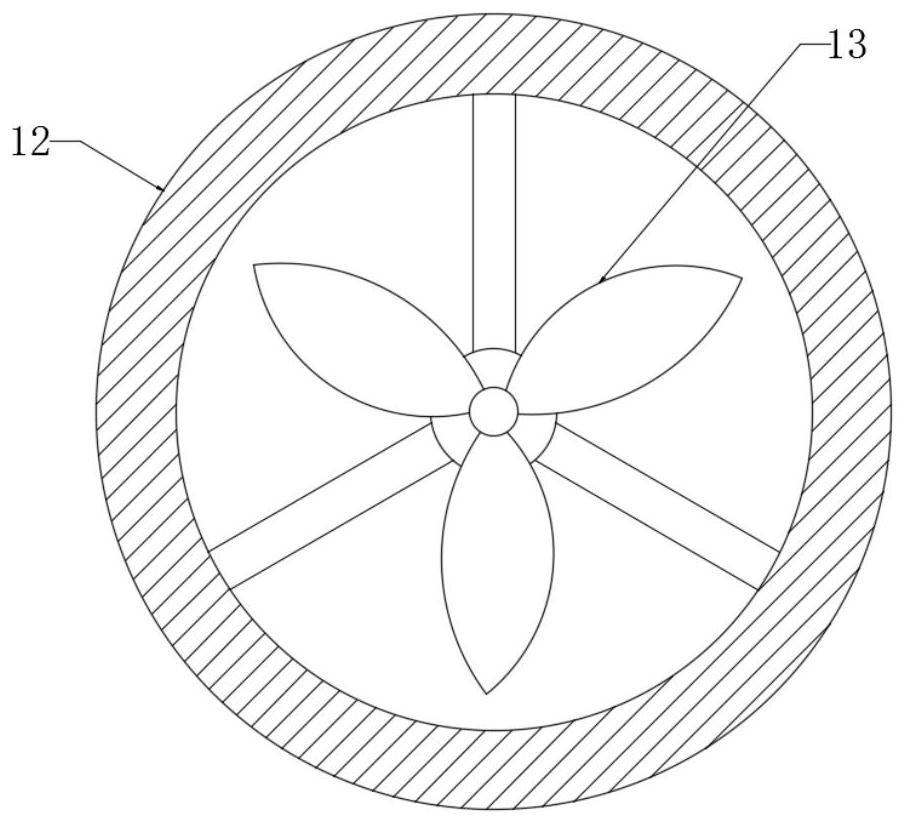
[0029]Embodiment 1: When the device is in use, if the gas pipe 5 leaks, the leaked gas will first be discharged between the outer protective pipe 1 and the inner protective pipe 3 through the vent hole 4, and the combustible gas sensor 26 close to the leaked gas will first It detects that the combustible gas content in the air exceeds the standard, and transmits the super standard signal to the control computer 21 through the data line 22, and then the control computer 21 judges the approximate location of the gas leakage according to the combustible gas sensor 26 that sends the signal, and then controls it through the control computer 21. The alarm horn 25 near the leak plays the alarm sound to remind the surrounding residents that the gas leakage occurs, so that it takes certain protective measures, and then the control computer 21 controls the ventilation fan 13 to start, and a part of the ventilation fan 13 sucks the outside air into the The inside of the outer protective t...
Embodiment 2
[0030] Embodiment 2: When more accumulated water is generated inside the outer protective tube 1, first the water level of the accumulated water rises and the buffer spring 18 is squeezed by the floating plate 19, and the floating plate 19 that floats up simultaneously squeezes the travel switch 20, so that The travel switch 20 is triggered, and the drainage pump 16 is started, so that the accumulated water inside the outer protection pipe 1 is pumped into the interior of the drainage pipe 17 through the drainage pump 16 through the water delivery pipe 15, and discharged from the surface 6 through the drainage pipe 17, thereby achieving automatic Control to avoid water accumulation inside the outer protective tube 1 .
Embodiment 3
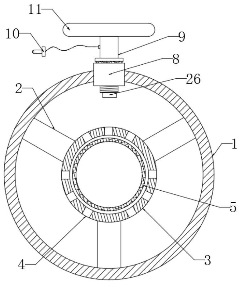
[0031] Embodiment 3: When the control computer 21 shows that there is a failure of the combustible gas sensor 26, by entering the inside of the maintenance tank 7 at the corresponding position, first disconnect the transmission plug 10 from the transmission socket 24, and then turn and adjust the hand dial 11 to make the installation The rod 9 rotates, so that the mounting rod 9 is separated from the threaded seat 8, and the combustible gas sensor 26 is taken out along with the mounting rod 9, so that the combustible gas sensor 26 can be easily repaired or replaced.
PUM
 Abstract
Description
Claims
Application Information
 - Generate Ideas
- Intellectual Property
- Life Sciences
- Materials
- Tech Scout
- Unparalleled Data Quality
- Higher Quality Content
- 60% Fewer Hallucinations
Browse by: Latest US Patents, China's latest patents, Technical Efficacy Thesaurus, Application Domain, Technology Topic, Popular Technical Reports.
© 2025 PatSnap. All rights reserved.Legal|Privacy policy|Modern Slavery Act Transparency Statement|Sitemap|About US| Contact US: help@patsnap.com