Supercharge Your Innovation With Domain-Expert AI Agents!

Drive circuit for closed-loop current sensor

A current sensor and drive circuit technology, applied in electrical components, measurement using digital measurement technology, output power conversion devices, etc., can solve the problem of not providing bipolar power supply and current signal sampling circuit, and the inapplicability of drive circuits, etc.

Pending Publication Date: 2021-01-08
JIANGSU CHANGRONG ELECTRICAL APPLIANCE CO LTD
View PDF0 Cites 0 Cited by
  • Summary
  • Abstract
  • Description
  • Claims
  • Application Information

AI Technical Summary

Problems solved by technology

In some industrial fields, such as the field of auto parts, almost no bipolar power supply and current signal sampling circuit is provided, so the above driving circuit is not applicable

Method used


Image

  • Drive circuit for closed-loop current sensor
  • Drive circuit for closed-loop current sensor
  • Drive circuit for closed-loop current sensor

Examples


Embodiment 1

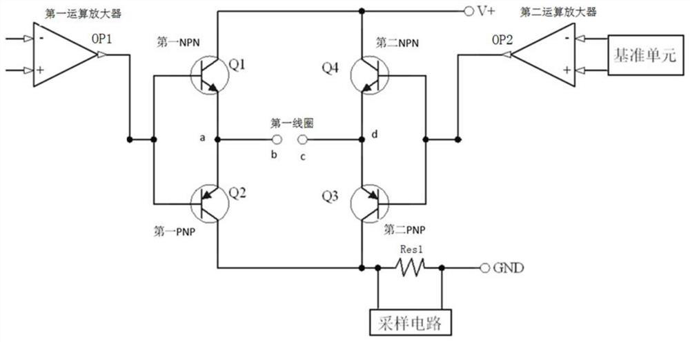
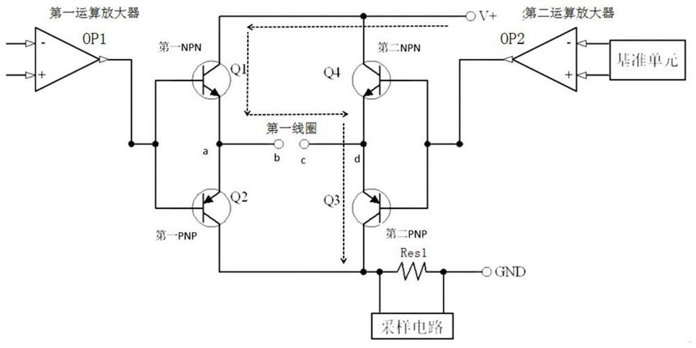
[0024] Embodiment 1: as figure 2 As shown, a driving circuit for a closed-loop current sensor includes a first operational amplifier OP1, a second operational amplifier OP2, M 1 A first NPN transistor Q1, M 2 A first PNP transistor Q2, M 3 A second NPN transistor Q4, M 4 A second PNP transistor Q3, sampling resistor Res1 and the first coil, M 1 , M 2 , M 3 , M 4 are all 1, where

[0025] The input terminal of the first operational amplifier OP1 is connected to an external input, and the output terminal of the first operational amplifier OP1 is respectively connected to the base of the first NPN transistor Q1 and the base of the first PNP transistor Q2. The emitter of an NPN transistor Q1 and the emitter of the first PNP transistor Q2 are connected to the b end of the first coil after the terminal a is connected, and the collector of the first NPN transistor Q1 and the collector of the second NPN transistor Q4 are respectively Connect the power supply V+, the emitter o...

Embodiment 2

[0031] Embodiment 2: as Figure 8 As shown, a driving circuit for a closed-loop current sensor includes a third operational amplifier OP3, a fourth operational amplifier OP4, K 1 A third NPN transistor Q5, K 2 A third PNP transistor Q6, K 3 A P-type MOSFET Q7, K 4 N-type MOSFET Q8, sampling resistor Res2 and the second coil, K 1 、K 2 、K 3 and K 4 are all 1, where

[0032] The input terminals of the third operational amplifier OP3 are respectively connected to external inputs, and the output terminals of the third operational amplifier OP3 are respectively connected to the base of the third NPN transistor Q5 and the base of the third PNP transistor Q6. The emitter of the three NPN transistor Q5 is connected to the B terminal of the second coil after the emitter of the third PNP transistor Q6 is connected to the A terminal, and the collector of the third NPN transistor Q5 is connected to the source of the P-type MOSFET Q7 respectively Power supply V+, the drain of the N-...


PUM


Abstract

The invention discloses a drive circuit for a closed-loop current sensor. The drive circuit comprises a first operational amplifier OP1, a second operational amplifier OP2, M1 first NPN triodes Q1, M2first PNP triodes Q2, M3 second NPN triodes Q4, M4 second PNP triodes Q3, a sampling resistor Res1 and a first coil. Under the power supply of an unidirectional power supply (V+ / GND), when primary side current is positive and when the primary side current is negative, the circuit can provide current in an opposite direction, so that an opposite compensation magnetic field is provided, the measurement of the current by the closed-loop current sensor is realized, and the bidirectional current measurement of the power supply of the unidirectional power supply is realized. In addition, when the polarity of the primary side current is changed, the voltage polarity at the two ends of the sampling resistor is kept unchanged and is always higher than the voltage of GND, so that the voltage can bedirectly sampled through ADC, and bias voltage is not needed.

Description

technical field [0001] The invention discloses a drive circuit for a closed-loop current sensor, which belongs to the field of sensor drive circuits. Background technique [0002] Existing high-precision current measurement technologies include closed-loop Hall, closed-loop AMR, closed-loop TMR technology, or closed-loop fluxgate technology. Such as figure 1 As shown, taking the closed-loop Hall technology as an example, it consists of an iron core with an air gap (and a secondary coil), a Hall unit, an operational amplifier, and a triode. When a current flows through the primary side, a magnetic field is generated in the air gap of the magnetic core, and the Hall unit outputs a voltage signal under the action of the magnetic field, and the voltage is amplified to drive the corresponding triode to supply power to the coil. Because the measured current is in two directions, the compensation coil needs compensation current in two directions, so the sensor needs a bipolar pow...

Claims


Application Information

Patent Timeline
IPC IPC(8): G01R19/25H02M1/088
CPCG01R19/25H02M1/088
Inventor 匡成效樊文露
Owner JIANGSU CHANGRONG ELECTRICAL APPLIANCE CO LTD
Features
  • R&D
  • Intellectual Property
  • Life Sciences
  • Materials
  • Tech Scout
  • Unparalleled Data Quality
  • Higher Quality Content
  • 60% Fewer Hallucinations
Learn More