Combing machine and working method of pre-spun yarn
A working method and combing technology, applied in the field of combing machines, can solve problems such as energy consumption, motor heating, etc.
- Summary
- Abstract
- Description
- Claims
- Application Information
AI Technical Summary
Problems solved by technology
Method used
Image
Examples
no. 1 example
[0024] The first embodiment ( Figure 1 to Figure 10 )
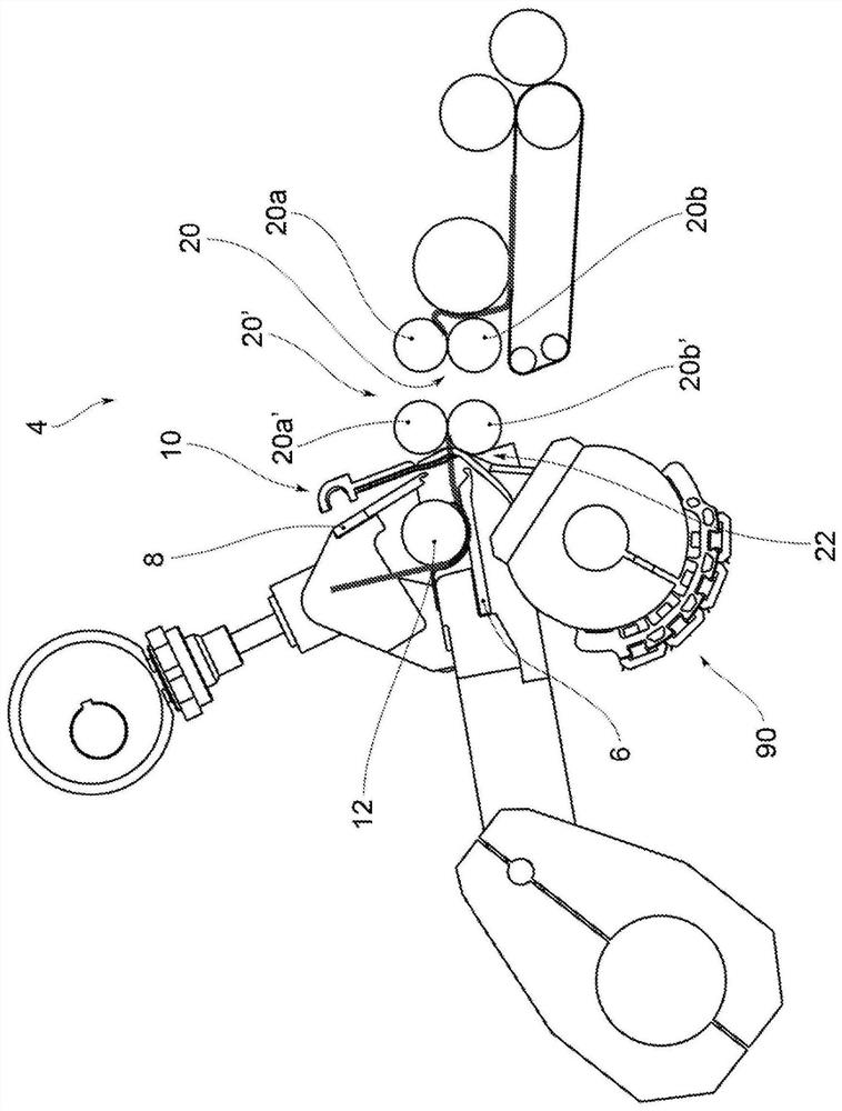
[0025] The combing machine according to the invention comprises a stationary frame and a plurality of combing heads, wherein each combing head comprises a nipper 4 supported by the stationary frame.
[0026] The tongs 4 include a lower jaw 6 , an upper jaw 8 and a straight comb 10 generally integral with the lower jaw 6 .
[0027] Furthermore, the jaw 4 includes a feed roller 12 supported by the lower jaw 6 , which can rotate in an intermittent manner on command.
[0028] The combing head also comprises at least one pair of separating rolls downstream of the nipper 4 .
[0029] For example, preferably immediately downstream of the tongs 4, in front of it, there is a pair 20' of superimposed (preferably in pressure contact) separating rollers 20a', 20b' with continuous rotational movement (with constant or Variable but irreversible speed), such as dragging a length of web protruding from the jaws, detaches the tufts ...
no. 2 example
[0086] The second embodiment ( Figure 11 )
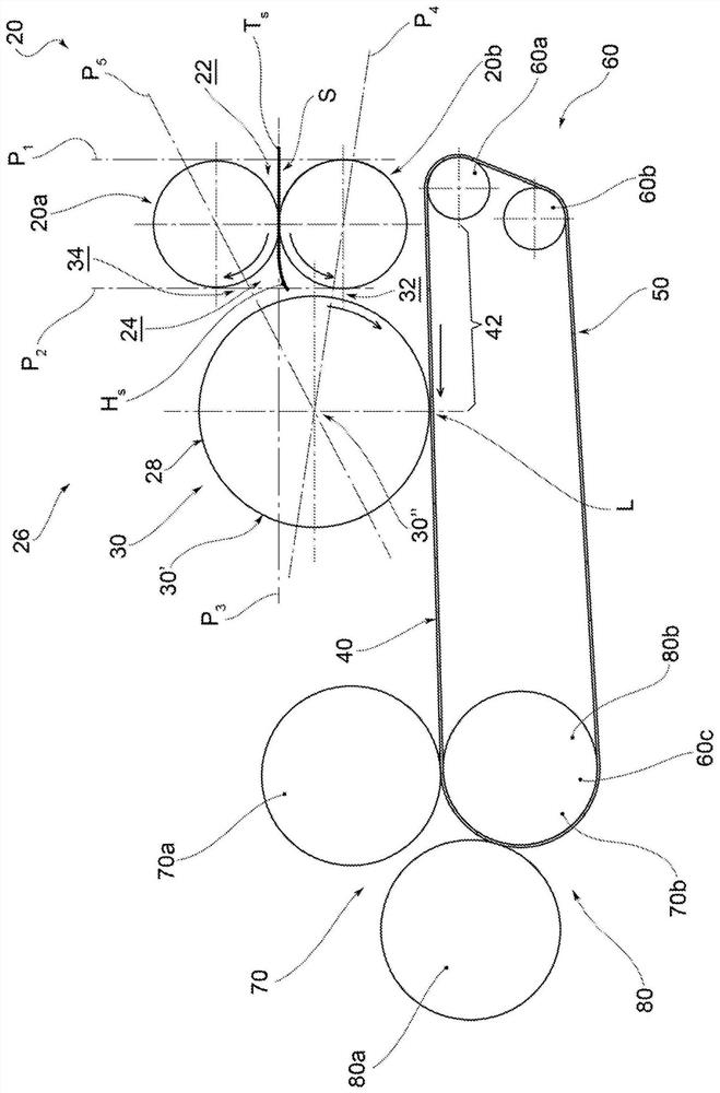
[0087] According to another embodiment substantially following the above, the transfer device 40 is engaged with the main surface 28 of the main device 26 by means of an arcuate engagement portion Ai, for example through an arcuate portion of the side surface 30' of the main roller 30, the arcuate The engagement portion is defined to cooperate with the transfer roller 200 .
[0088] For example, the path of the belt 50 of the transfer device 40 is defined by said transfer rollers 200 .
[0089] In this embodiment, the tufts S' (and thus the combed wire) are not detached from the main surface 28 to move unsupported towards the transfer device 40, but only at the arcuate junction when they have been supported by the transfer device 40. The ends of Ai are separated from the main surface 28 .
no. 3 example
[0090] The third embodiment ( Figure 12 )
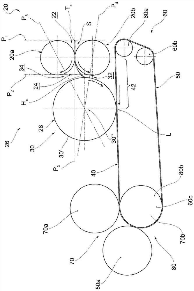
[0091] According to another embodiment substantially following what has been described above, the primary device 26 comprises a primary belt 100 movable along a closed path facing the outlet ports 24 of the auxiliary rollers 20a, 20b.
[0092] For example, the path of the main tape 100 is defined by a lower main roll 102 and an upper main roll 104 on which the main tape 100 is wound.
[0093] The main belt 100 has an outer surface forming said main surface 28 of the main device 26 in a stretch in front of the outlet port 24 against which the tufts from the auxiliary rollers 20a, 20b strike.
[0094] A portion of the main surface 28 forms the impact area.
[0095] The main surface 28 is airtight, ie no holes or gaps are provided for the suction flow intended to retain the tufts transported by said main surface.
PUM
 Abstract
Description
Claims
Application Information
 - R&D
- Intellectual Property
- Life Sciences
- Materials
- Tech Scout
- Unparalleled Data Quality
- Higher Quality Content
- 60% Fewer Hallucinations
Browse by: Latest US Patents, China's latest patents, Technical Efficacy Thesaurus, Application Domain, Technology Topic, Popular Technical Reports.
© 2025 PatSnap. All rights reserved.Legal|Privacy policy|Modern Slavery Act Transparency Statement|Sitemap|About US| Contact US: help@patsnap.com


