Electric tool with separable working head with intelligent identification

An intelligent identification, power tool technology, applied in the direction of manufacturing tools, portable mobile devices, etc., can solve the problems of increasing consumer costs, damage to work heads, material waste, etc., to achieve good fixing effects, reduce costs, and ensure continuous use. Effect

Pending Publication Date: 2021-01-12
NINGBO NEWPORT TOOLS +1
View PDF0 Cites 2 Cited by
  • Summary
  • Abstract
  • Description
  • Claims
  • Application Information

AI Technical Summary

Problems solved by technology

[0003] Hand-held electric tools are machines that control the motor to drive the working head to realize mechanized operation. At present, the working head and the motor are integrated in the design and fixed to the driving handle for integration, so that it can be carried to the workplace and operated by hand. , but the above-mentioned structure has the following disadvantages: First, wear and tear is unavoidable in the working process of the working head. Excessive wear and tear under frequent use can easily damage the working head. The integrated design causes the entire electric tool to be discarded after the working head is damaged. Consumers have to re-purchase the entire electric tool, but at this time, the motor in the drive handle (especially the brushless motor, which itself has the characteristics of long service life) switches, controllers and other components are often intact and usable, while These parts often account for 80% of the total cost of electric tools, which means that when the electric tools are scrapped, the electric tools are not used well, which not only causes waste of materials, but also increases the cost of consumers ;Secondly, for the occasions where different types of power tools are needed due to the diversification of operations, the integrated design makes consumers need to prepare a variety of power tools related to the job, and a large number of power tools increases the consumption when carrying them. The burden of consumers, the same purchase of a variety of electric tools will further increase the cost of consumers

Method used


Image

  • Electric tool with separable working head with intelligent identification
  • Electric tool with separable working head with intelligent identification
  • Electric tool with separable working head with intelligent identification

Examples


Embodiment 1

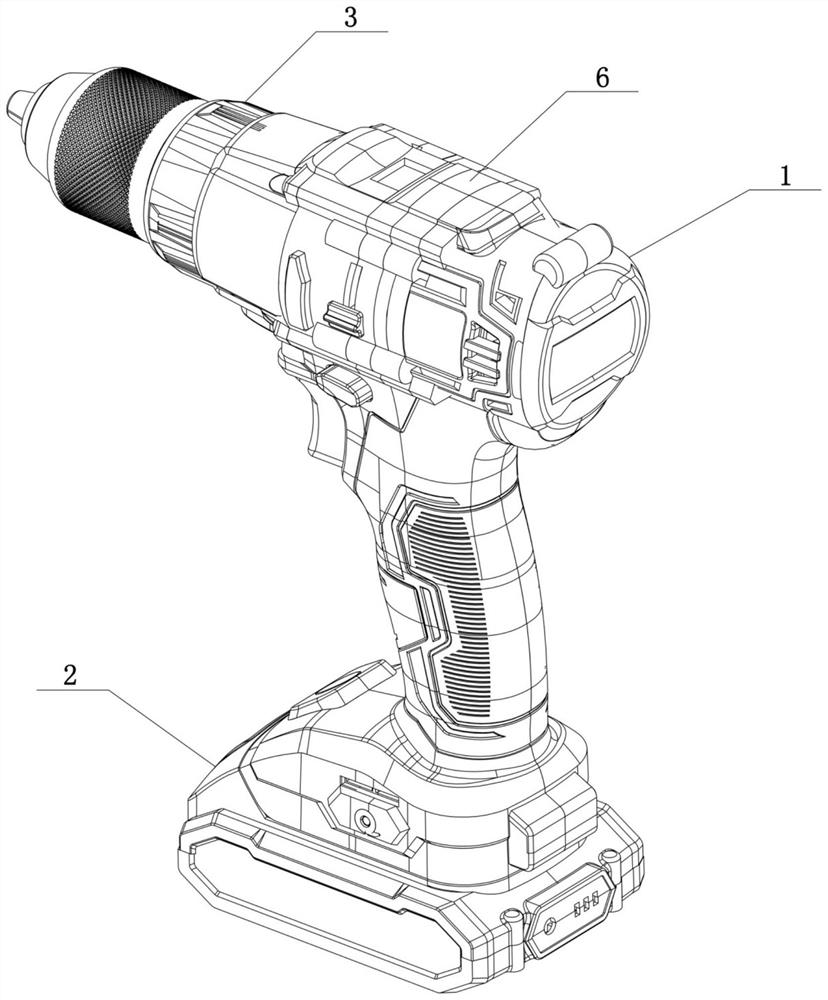
[0054] Such as figure 1 , figure 2 , Figure 5 to Figure 13 As shown, an electric tool with a detachable working head is mainly aimed at occasions where the work cannot be carried out due to damage to the working head 5 and the whole machine needs to be replaced urgently, or where different types of tools are required due to the diversification of the work. In the case of electric tools.

[0055] It includes: a driving handle 1, a power supply part 2 for power supply on the driving handle 1, and a controller 3 for command processing;

[0056] The controller 3 includes a single-chip microcomputer. The single-chip microcomputer has the characteristics of high integration, small size, good reliability, rich instructions, and strong control ability, and can well assist the electric tool of this technical solution to realize the following functions.

[0057] It also includes: motor 4, working head 5, assembly and disassembly assembly 6, sensed element 7 and sensing element 8, b...

Embodiment 2

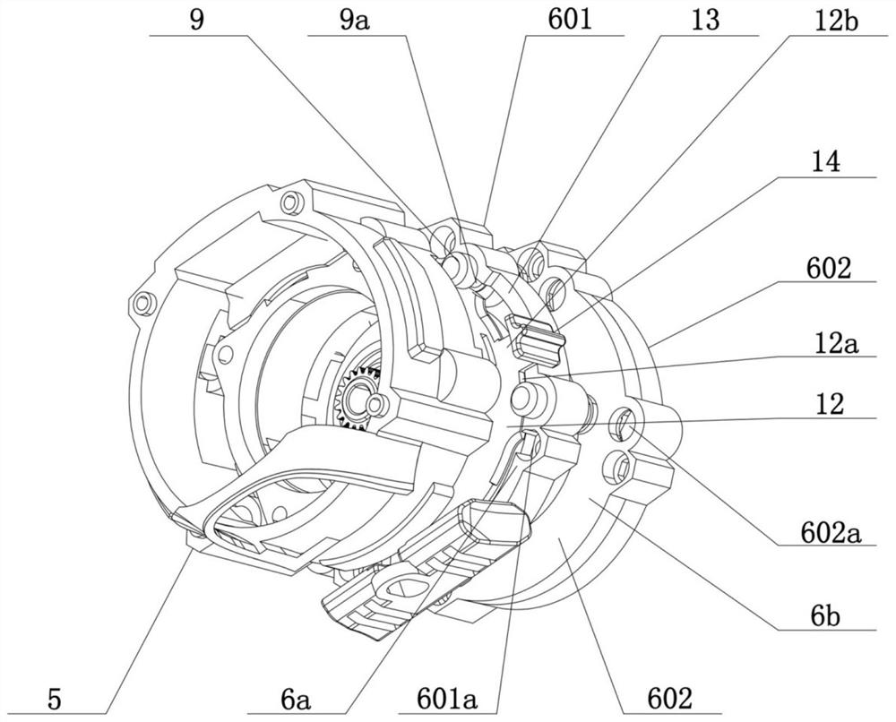
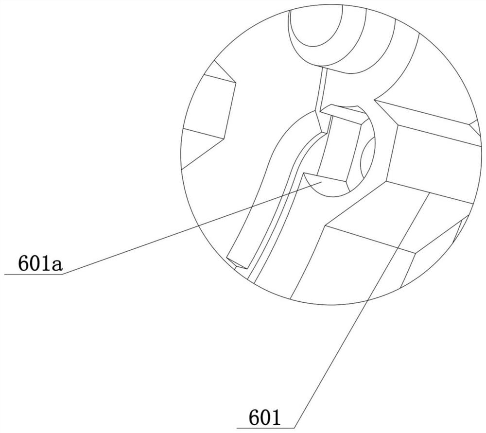
[0073] Such as Figure 5 to Figure 13 As shown, in this embodiment, on the basis of the above-mentioned embodiment 1, one of the optimized designs is made, and the mounting and dismounting parts 6b of the front end retainer 601 and the rear end retainer 602 are provided with opposite first slots 601b and second slots respectively. Two slots 602b, the sensed element 7 and the sensing element 8 are installed in the first slot 601b and the second slot 602b respectively, through the above settings, the sensed element 7 and the sensing element 8 can always be fixed in one and the front end The relatively fixed positions of the frame 601 and the rear end holder 602 avoid the situation that the induction element 8 in the drive handle 1 cannot sense the induction element 8 when the front end holder 601 is fixed on the drive handle 1 along with the working head 5 .

Embodiment 3

[0075] Such as Figure 6 and Figure 7 As shown, in this embodiment, one of the optimized designs is made on the basis of the above-mentioned embodiment 1. The driving handle 1 includes a left casing 101 and a right casing 102 which are arranged side by side and have through grooves formed inside, and the two through grooves are on the left The housing 101 and the right housing 102 are fixed to form a through cavity, so as to accommodate the motor 4 , the sensing element 8 , the switch 15 and the controller 3 in the through cavity.

[0076] Further, the through cavity includes a first open end 1a located on the upper part of the left housing 101 and the right housing 102, and the first open end 1a is closed by the limiting part 6a of the assembly and disassembly assembly 6, so that the motor 4 is sealed to the driving handle 1 the upper end.

[0077] Further, the through cavity also includes a second open end 1b located at the bottom of the left housing 101 and the right hou...


PUM


Abstract

The invention relates to an electric tool with a separable working head with intelligent identification. The electric tool comprises a driving handle with a power supply part and a controller, and further comprises a motor, a working head, an assembling and disassembling assembly, a sensed element and a sensing element, the motor is arranged in the driving handle, the rotating speed is controlledby the controller, the working head is driven by the motor and detachably arranged on the driving handle in a state of being opposite to the motor, the assembling and disassembling assembly comprisesa limiting part connected with the working head and the motor and a detachably fixed assembling and disassembling part, the sensed element is arranged in the assembling and disassembling assembly fixed to the working head and is prefabricated with parameter information matched with the type of the working head, the sensing element is arranged in the driving handle corresponding to the position ofthe sensed element and used for sensing preset parameters in the sensed element and sending the parameters to the controller, and the controller carries out corresponding program control on the motor.According to the technical scheme, the working head and the driving handle are designed in a split mode, and the same driving handle can be matched with different types of working heads.

Description

technical field [0001] The invention relates to an electric tool, more specifically an electric tool equipped with a detachable working head with intelligent identification. Background technique [0002] Hand-held power tools are loved by consumers due to their high work efficiency, and have become one of the most widely used tools in work and life. They can be divided into hand-held gun drills, hand-held impact wrenches, hand-held electric impact Scissors, hand-held angle grinders, hand-held impact screwdrivers, hand-held polishing machines, etc. [0003] Hand-held electric tools are machines that control the motor to drive the working head to realize mechanized operation. At present, the working head and the motor are integrated in the design and fixed to the driving handle for integration, so that it can be carried to the workplace and operated by hand. , but the above-mentioned structure has the following disadvantages: First, wear and tear is unavoidable in the working...

Claims


Application Information

Patent Timeline
Patent Type & Authority Applications(China)
IPC IPC(8): B25F5/00
CPCB25F5/00B25F3/00
Inventor 罗小军
Owner NINGBO NEWPORT TOOLS
Why Eureka
Try Eureka