
Crane cart walking emergency safety braking device and method

A technology for safe braking and cranes, applied in the direction of safety devices, traveling mechanisms, drum brakes, etc., can solve problems such as sliding into the maintenance section, increasing the electronic control of the crane's traveling braking system, damage to braking machinery, and equipment damage

Active Publication Date: 2021-01-12
WUHU XINXING DUCTILE IRON PIPES
View PDF8 Cites 0 Cited by
  • Summary
  • Abstract
  • Description
  • Claims
  • Application Information

AI Technical Summary

Problems solved by technology

[0004] Phenomenon 1: In the same operation, multiple cranes are selected for operation across the design, and at the same time they are used as backups for each other. However, in actual work, in order to realize the rapid and accurate positioning and parking of the cranes, reduce the operation time of the unit product, and improve the operation efficiency, the crane workers are in operation. Reverse driving (commonly known as returning the car) is often used to pre-control the crane and lift heavy objects, so as to realize positioning parking (that is, when the crane is moving forward, the braking force generated by the rotation of the driving motor of the crane is used to brake and position). This operation method similar to emergency braking artificially increases the damage of the electric control and braking machinery of the crane travel braking system. Like the emergency braking system of a truck, frequent use of emergency braking mode will affect the overall service life and safety of the crane. have a great impact
[0005] Phenomenon 2: When the same operation crosses sections, there is a mandatory requirement for the cranes in the maintenance section to stop the power supply of the contact line before they can be overhauled. In the case of entering the maintenance section (marked line without power supply state)
A crane that does not brake in time hits a crane in an overhaul state, which will cause equipment damage or personal injury or death in the overhaul state.
[0006] Phenomenon 3: During the loading and unloading process of the crane, there is a sudden power failure or a sudden power failure at the marking line. Because the crane brake is too loose (manually adjusted), the power failure and the reverse brake cannot be applied, causing the crane to slide and hit the adjacent crane or other structures. , resulting in equipment damage or personal injury or death

Method used


Image

  • Crane cart walking emergency safety braking device and method
  • Crane cart walking emergency safety braking device and method
  • Crane cart walking emergency safety braking device and method

Examples


Embodiment Construction

[0029] Specific embodiments of the present invention will be described in detail below in conjunction with the accompanying drawings. It should be understood that the specific embodiments described here are only used to illustrate and explain the present invention, and are not intended to limit the present invention.

[0030] In the present invention, unless stated otherwise, the orientation words included in the term such as "up, down, left, and right" only represent the orientation of the term in the normal use state, or the common name understood by those skilled in the art, rather than should be considered a limitation of the term.

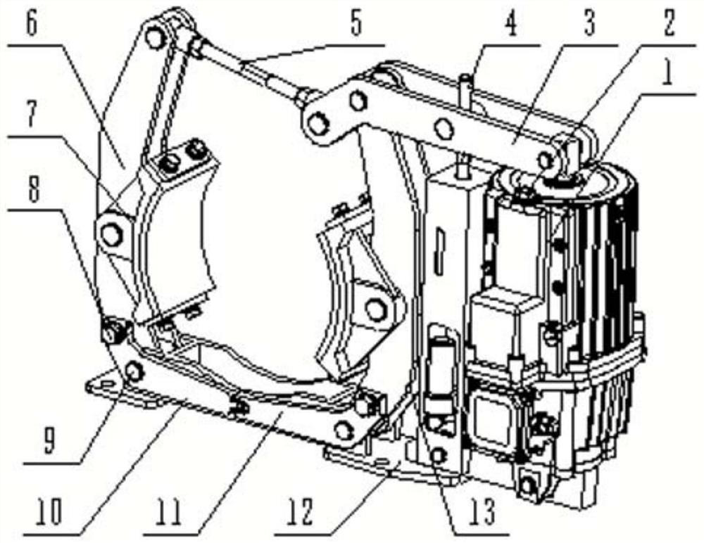
[0031] The present invention provides an emergency safety braking device for cranes and carts, which is an improvement when there is a first brake in the prior art. Since there are only the first brakes, various safety hazards are likely to occur, such as image 3 As shown, the emergency safety braking device for heavy machinery and carts may...


PUM


Abstract

The invention discloses a crane cart walking emergency safety braking device. The crane cart walking emergency safety braking device comprises a first brake, a second brake, a power distribution cabinet and a manual controller, a power distribution cabinet used for carrying out frequency conversion adjustment on a motor of a pusher of the second brake, and a manual controller electrically connected to the power distribution cabinet, wherein the first brake and the second brake are used for controlling the braking condition of a crane; the manual controller is used for adjusting a motor of thesecond brake through the power distribution cabinet according to an operation signal from a user for the manual controller when the gear of the crane is in a driving gear, so that the braking condition of the crane is adjustable; ad when the gear of the crane is in a parking gear, the manual controller cannot control the second brake. The crane cart walking emergency safety braking device providedby the invention can avoid and reduce potential safety hazards.

Description

technical field [0001] The invention relates to the field of safety management of cranes, in particular to an emergency safety brake device and method for traveling a crane cart. Background technique [0002] At present, the general-purpose crane trolley travel control system often uses electromagnetic or electro-hydraulic control system and supporting equipment to realize the braking and positioning of the crane travel position. Mechanical braking of the crane travel drive shaft to realize the parking function of the crane. Since the electromagnetic suction force or the output thrust of the electro-hydraulic pusher cannot be continuously adjusted (0 or 1), the braking torque applied by the braking device to the driving shaft of the crane during braking is constant, and adjustable and variable braking cannot be realized. torque, resulting in a lot of vibration when parking, especially when lifting and handling large-tonnage heavy objects. [0003] The loading of the heatin...

Claims


Application Information

Patent Timeline
Patent Type & Authority Applications(China)
IPC IPC(8): B66C9/18B66C15/00F16D49/16F16D65/16F16D66/02F16D121/24
CPCB66C9/18B66C15/00F16D49/16F16D65/16F16D66/022F16D2121/24
Inventor 宋红伟王有为李中刘洪亮
Owner WUHU XINXING DUCTILE IRON PIPES
Learn More