Automatic efficient building earth ramming device

A construction and rammed earth technology, applied in the field of automatic and efficient construction rammed earth devices, can solve problems such as dust flying, respiratory tract injury, arm numbness, etc., and achieve the effect of avoiding dust flying and reducing dust

Inactive Publication Date: 2021-01-12
聂伟
View PDF5 Cites 0 Cited by
  • Summary
  • Abstract
  • Description
  • Claims
  • Application Information

AI Technical Summary

Problems solved by technology

[0002] The tamping machine is a kind of machine used for compaction. Its principle is to drive the tamping plate under the drive of the motor to achieve the effect of impact and vibration to achieve the effect of tamping the ground. In the construction site and early road repair, because of its simple structure, it is easy to operate. , Get started quickly, and the tamping machine has become the most commonly used mechanical equipment, but in hot or dry environments, when the staff is in the process of tamping, the tamping machine will generate a lot of dust, and the machine has not worked for a while. The dusty situation is caused, which not only affects the environment, but also the staff will inhale the dust in such an environment, which will cause damage to the respiratory tract. When the dust is large, because the engine of the rammer is exposed to the outside, the dust will enter the engine , if working at a high temperature, the degree of wear between the parts will be greatly increased, resulting in damage to the engine, and the hand-held device of the conventional rammer is connected with the body, and the vibration will drive the hand-rail device to move together , when some older workers operate, their arms will be numb after a short working time, and they need to stop and rest for a while before continuing to work, but today's construction and road construction are developing faster and faster , we need to improve our work efficiency

Method used


Image

  • Automatic efficient building earth ramming device
  • Automatic efficient building earth ramming device
  • Automatic efficient building earth ramming device

Examples


Embodiment Construction

[0024] In order to further illustrate the various embodiments, the present invention provides accompanying drawings, which are part of the disclosure of the present invention, and are mainly used to illustrate the embodiments, and can be used in conjunction with the relevant descriptions in the specification to explain the operating principles of the embodiments, for reference Those of ordinary skill in the art should be able to understand other possible implementations and advantages of the present invention. The components in the figures are not drawn to scale, and similar component symbols are generally used to represent similar components.

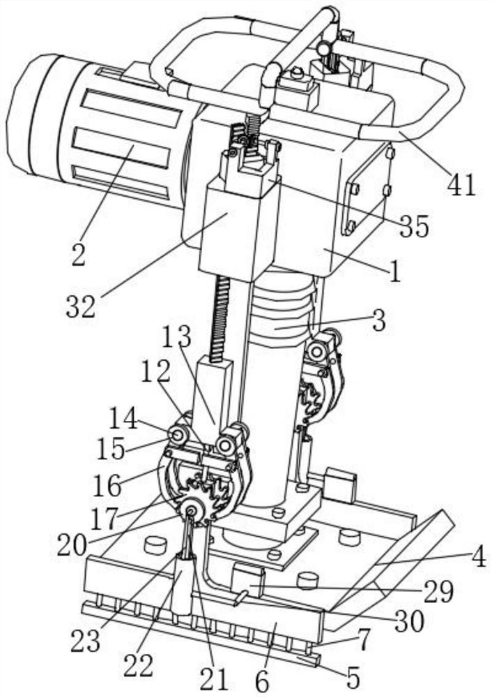
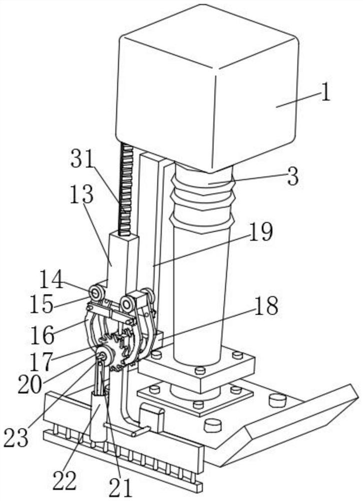
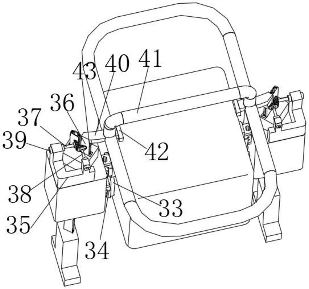
[0025] According to an embodiment of the present invention, an automatic high-efficiency building ramming device is provided, such as Figure 1 to Figure 5 As shown, among them.

[0026] Figure 1-5 It is a structural device diagram of an automatic high-efficiency building ramming device according to an embodiment of the present inven...


PUM


Abstract

The invention discloses an automatic efficient building earth ramming device which comprises a machine body, a motor is arranged on one side of the machine body, a ramming frame is arranged at the bottom end of the machine body, a rammer is connected to the bottom end of the ramming frame, spring plates are arranged on the two sides of the rammer, T-shaped baffles are arranged at the top ends of the spring plates, and strong springs are arranged between the spring plates and the T-shaped baffles. Annular grooves are formed in the T-shaped baffles. The ramming device has the advantages that when the ramming device is used on a building, dust can be purified through the vibration effect of the ramming device, dust flying and discomfort to the environment and the body of a constructor in theconstruction process are effectively avoided, meanwhile, a buffer device is additionally arranged on a handrail of the constructor, the construction comfort of workers is effectively improved, and theworking time is improved.

Description

technical field [0001] The invention relates to the field of building construction, in particular to an automatic high-efficiency building ramming device. Background technique [0002] The tamping machine is a kind of machine used for compaction. Its principle is to drive the tamping plate under the drive of the motor to achieve the effect of impact and vibration to achieve the effect of tamping the ground. In the construction site and early road repair, because of its simple structure, it is easy to operate. , Get started quickly, and the tamping machine has become the most commonly used mechanical equipment, but in hot or dry environments, when the staff is in the process of tamping, the tamping machine will generate a lot of dust, and the machine has not worked for a while. The dusty situation is caused, which not only affects the environment, but also the staff will inhale the dust in such an environment, which will cause damage to the respiratory tract. When the dust is...

Claims


Application Information

Patent Timeline
Patent Type & Authority Applications(China)
IPC IPC(8): E01C19/38E02D3/068E02D3/02E01H3/02
CPCE01C19/38E01H3/02E02D3/02E02D3/068
Inventor 不公告发明人
Owner 聂伟
Why Eureka
Try Eureka