
Cleaning equipment for sewage inspection well in urban underground pipe gallery

A technology for underground pipe gallery and cleaning equipment, which is applied in the field of inspection well cleaning, and can solve the problems of time-consuming, laborious and uncertain factors

Inactive Publication Date: 2021-01-12
周宗银
View PDF7 Cites 4 Cited by
  • Summary
  • Abstract
  • Description
  • Claims
  • Application Information

AI Technical Summary

Problems solved by technology

[0002] Sewage, usually refers to certain polluted discharge water from domestic and production. Sewage mainly includes domestic sewage, industrial wastewater and initial rainwater. The main pollutants of sewage include pathogen pollutants, oxygen-consuming pollutants, plant nutrients and toxic pollution. From the point of view of the source of sewage, sewage can be defined as liquid or water mixed with groundwater, surface water, snowstorms, etc. discharged from residences, institutions, commercial or industrial areas and mixed with waste. Sewage treatment requires the use of pipelines, while The pipe gallery formed by the combination of many pipelines often needs to use the sewage inspection well in the actual use of the pipe gallery. The manual cleaning of the sediment in the sewage well is time-consuming and laborious, and there are too many uncertain factors. It is easy to cause harm to the staff, so we need a cleaning equipment for the sewage inspection well in the urban underground pipe gallery. This equipment can carry out sludge adsorption and flushing on the sewage well by itself, reducing labor while ensuring the safety of workers and avoiding unnecessary losses.

Method used


Image

  • Cleaning equipment for sewage inspection well in urban underground pipe gallery
  • Cleaning equipment for sewage inspection well in urban underground pipe gallery
  • Cleaning equipment for sewage inspection well in urban underground pipe gallery

Examples


Embodiment Construction

[0080]The following description is used to disclose the present invention so that those skilled in the art can implement the present invention. The preferred embodiments in the following description are only examples, and those skilled in the art can think of other obvious variations.

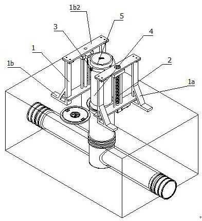
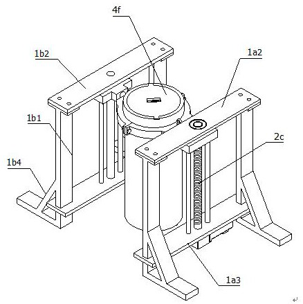
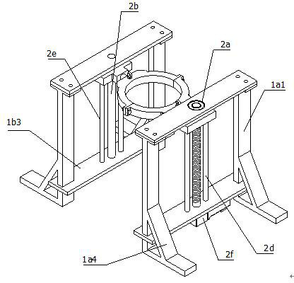
[0081]ReferenceFigure 1 to Figure 10As shown, a cleaning equipment for a sewage inspection well in an urban underground pipe gallery is characterized in that it includes:

[0082]Frame 1, used to install components;

[0083]The lifting assembly 2 is fixedly installed with the frame 1. The lifting assembly 2 is installed in the frame 1 in a vertical state, and the lifting assembly 2 is used to drive the lifting work;

[0084]The clamping assembly 3 is fixedly installed with the lifting assembly 2, and the clamping assembly 3 is fixedly installed at the output end of the lifting assembly 2;

[0085]The cleaning mechanism 4 is fixedly installed at the output end of the clamping assembly 3, and the cleaning mechanism 4...


PUM


Abstract

The invention relates to the field of inspection well cleaning, in particular to cleaning equipment for a sewage inspection well in an urban underground pipe gallery. The cleaning equipment is characterized by comprising a rack, a lifting assembly, a hooping assembly, a cleaning mechanism, a filtering mechanism and a scouring mechanism, wherein the rack is used for mounting an assembly; the lifting assembly and the rack are fixedly installed, the lifting assembly is vertically arranged in the rack, and the lifting assembly is used for driving lifting work; the hooping assembly and the liftingassembly are fixedly installed, and the hooping assembly is fixedly installed at the output end of the lifting assembly; the cleaning mechanism is fixedly installed at the output end of the hooping assembly, and the cleaning mechanism is used for adsorbing sludge at the bottom of the well; the filtering mechanism and the cleaning mechanism are fixedly installed, the filtering mechanism is arrangedin the cleaning mechanism, and the filtering mechanism is used for filtering sludge; and the scouring mechanism is fixedly installed at the output end of the cleaning mechanism and used for scouringand diluting sludge at the bottom of the well. The equipment can automatically adsorb and scour the sludge in a sewage well, the safety of workers is guaranteed while manpower is reduced, and unnecessary losses are avoided.

Description

Technical field[0001]The invention relates to the field of inspection well cleaning, in particular to a cleaning equipment for sewage inspection wells in urban underground pipe corridors.Background technique[0002]Sewage usually refers to certain polluted water discharged from life and production. Sewage mainly includes domestic sewage, industrial wastewater and initial rainwater. The main pollutants of sewage include pathogen pollutants, oxygen-consuming pollutants, plant nutrients and toxic pollution. From the perspective of the source of sewage, sewage can be defined as liquid or water that is mixed with groundwater, surface water, blizzards, etc., discharged from residential, government, commercial or industrial areas and carries waste. The sewage treatment requires the use of pipes, and The pipe gallery formed by the combination of many pipelines, the pipe gallery often needs to use sewage inspection wells in the actual use process. The manual cleaning of the sedimentation sludg...

Claims


Application Information

Patent Timeline
IPC IPC(8): E03F7/00E03F9/00B01D29/05B01D29/56B01D36/04
CPCB01D29/05B01D29/56B01D36/04E03F7/00E03F9/00E03F9/007
Inventor 周宗银
Owner 周宗银
Learn More