
Cooperative control system of air compressor unit

An air compressor unit, collaborative control technology, applied in pump control, mechanical equipment, machine/engine, etc., can solve problems such as increased equipment loss, reduced air compressor life, increased labor costs, etc., to improve safety performance, extend Long service life and good control effect

Inactive Publication Date: 2021-01-12
苏州合卓智能科技有限公司
View PDF5 Cites 6 Cited by
  • Summary
  • Abstract
  • Description
  • Claims
  • Application Information

AI Technical Summary

Problems solved by technology

When the air consumption of the system increases, it is obvious that one air compressor cannot meet the production demand, so we need to turn on another air compressor at this time, but since the current air compressors are all stand-alone systems, only It is an artificial start-up to increase the number of machines. If the air consumption changes greatly in a day, the maintenance personnel of the factory need to constantly change the number of air compressors according to the pressure of the air supply main pipe to achieve energy saving costs. Although this method Energy saving, but it greatly increases labor costs and brings great inconvenience to maintenance personnel
If all the air compressors are fully turned on, the maintenance personnel do not need to worry about pressure changes, and let all the air compressors load and stand by according to the parameters set by themselves, but then another problem arises. When all the air compressors are fully turned on, the main pipe The exhaust capacity is also increasing, so when the exhaust pressure is lower than the target exhaust pressure, multiple air compressors will soon reach the automatic shutdown pressure, because the total exhaust capacity is too strong, the air compressor will frequently Start and stop, although it can meet the changing air consumption in a day, but the frequent start and stop of the air compressor greatly reduces the life of the air compressor, increases the loss of equipment, and increases maintenance costs, so we urgently need an accessory control system , to solve the above two contradictory problems, so that all air compressors can not only work as a single machine, but also work together with multiple machines without being on duty

Method used


Image

  • Cooperative control system of air compressor unit

Examples


Embodiment Construction

[0033] The following will clearly and completely describe the technical solutions in the embodiments of the present invention with reference to the accompanying drawings in the embodiments of the present invention. Obviously, the described embodiments are only some, not all, embodiments of the present invention. Based on the embodiments of the present invention, all other embodiments obtained by persons of ordinary skill in the art without making creative efforts belong to the protection scope of the present invention.

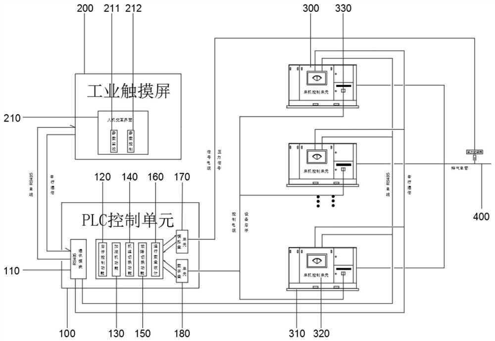
[0034] see figure 1 , the present invention provides a technical solution: an air compressor unit cooperative control system, including a PLC control unit 100, an industrial touch screen 200, an air compressor unit 300 and an exhaust manifold 400, the PLC control unit 100 is connected to the air compressor unit 300, and the PLC The control unit 100 can store and update the operating status of each air compressor 300 to its internal database in real time;

[0...


PUM


Abstract

The invention discloses a cooperative control system of an air compressor unit. The cooperative control system comprises a PLC control unit, an industrial touch screen, an air compressor unit and an exhaust manifold, wherein the air compressor unit is formed by combining a plurality of air compressors, the air compressor unit is connected with the exhaust manifold, the PLC control unit is connected with the air compressor unit and used for driving the air compressors to be started and stopped, the PLC control unit is further connected with the exhaust manifold and used for collecting pressurevalues in the exhaust manifold in real time, the industrial touch screen comprises a human-computer interaction interface used for setting a target exhaust pressure value, setting the maximum operation time of the air compressors, receiving the pressure value collected by the PLC control unit and calculating and comparing the pressure value with the target exhaust pressure value; the PLC control unit comprises a RS485 communication module which is connected with the industrial touch screen and the air compressor unit through a RS485 bus, and used for transmitting real-time operation parametersof the air compressor unit to the industrial touch screen to be displayed; and a start and stop control function module is used for controlling start and stop of the air compressors. According to thecooperative control system of the air compressor unit, cooperative control over the air compressor unit is facilitated, and control is stable.

Description

technical field [0001] The invention relates to the technical field of air compressor control, in particular to a cooperative control system of an air compressor unit. Background technique [0002] In recent years, factory production safety awareness has increased, and more and more factories have begun to abandon the original electric production equipment for explosion-proof and safety considerations, and began to use pneumatic-powered production tools and production equipment, especially for some flammable production equipment. Explosive chemical gas factories pay more attention to the production equipment powered by compressed air, so the compressed air production equipment "air compressor" has been purchased and used by more and more factories. [0003] At present, most of the air compressors sold in the market are equipped with a stand-alone automatic control system, which can adjust the load by itself according to the exhaust pressure of its own stand-alone unit. When ...

Claims


Application Information

Patent Timeline
Patent Type & Authority Applications(China)
IPC IPC(8): F04B49/06F04B49/02F04B49/10
CPCF04B49/065F04B49/02F04B49/10
Inventor 崔小强钟文俊
Owner 苏州合卓智能科技有限公司
Learn More