
Biomass marsh gas preprocessing system

A pretreatment and biomass technology, applied in the pipeline system, gas/liquid distribution and storage, fire rescue, etc., can solve the problem of low utilization rate of biogas

Inactive Publication Date: 2006-11-22
NANJING UNIV
View PDF0 Cites 6 Cited by
  • Summary
  • Abstract
  • Description
  • Claims
  • Application Information

AI Technical Summary

Problems solved by technology

[0005] The purpose of this invention is to design a biomass biogas pretreatment system that can provide qualified biogas fuel for generators or boilers in view of the current situation that the utilization rate of biogas is not high due to the lack of biogas pretreatment system

Method used


Image

  • Biomass marsh gas preprocessing system

Examples


Embodiment Construction

[0019] The present invention will be further described below in conjunction with the accompanying drawings and embodiments.

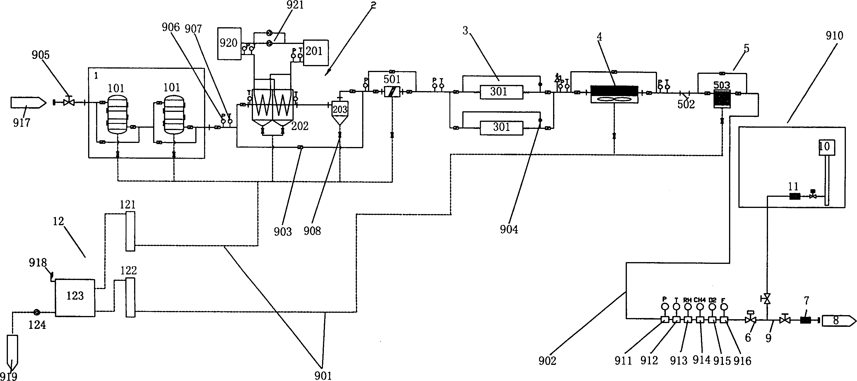
[0020] As shown in Figure 1.

[0021] A biomass biogas pretreatment system, which mainly consists of a desulfurization device 1 composed of two desulfurization tanks 101 connected in series, a water cooler 201, a two-stage shell-and-tube heat exchanger 202, and a cyclone dehydrator 203 Water-cooled biogas dehydration device 2, a Roots blower device composed of two Roots blowers 301 and two self-operated micro-pressure regulators 302 3, an air-cooled radiator 4, a primary filter 501, and a pipeline aisle filter device 5 composed of device 502 and coalescing filter 503, an electromagnetic cut-off valve 6, and a pipeline flame arrester 7; wherein the input end of desulfurization device 1, that is, the input end of desulfurization tank 101, is connected to the biogas pipeline, and the desulfurization device 1 The output end, that is, the output end of the ...


PUM


Abstract

The invention relates to a biological miasma pretreatment system for supplying miasma fuel to the generator or boiler. It is characterized in that: it comprises a desulfurizer (1), a water-cold miasma dewater device (2), a Root fan (3), a wind-cold heat emitter (4), a filter (5), an electromagnetic cut-off valve (6), and a channel fire arrester (7). The invention can solve the problems as corrosion and short service life.

Description

technical field [0001] The invention relates to a biogas treatment device, in particular to a biogas treatment device for providing qualified biogas fuel for thermal power plants, in particular to a biomass biogas pretreatment system. Background technique [0002] As we all know, the main component of biomass biogas is methane. As a strong greenhouse gas, its emission to the air is a great pollution to the environment. At the same time, methane is also a clean energy source, and it has been widely used in power generation, boilers, and pipeline gas supply abroad. With the development of my country's industry and agriculture and the acceleration of urbanization, industrial wastewater treatment, urban domestic waste landfill, agricultural and animal husbandry composting, etc. have brought abundant raw materials to the generation of biomass methane. At present, domestic biomass biogas utilization projects are in the ascendant, and related projects have been launched in more th...

Claims


Application Information

Patent Timeline
Patent Type & Authority Applications(China)
IPC IPC(8): F17D1/02A62C4/02F17D3/01F17D3/10F17D3/14
Inventor 陈泽智龚惠娟唐秋萍刘鹏许雪松
Owner NANJING UNIV
Learn More