Valve with anti-freezing function

A valve and function technology, applied in the field of valves with anti-freeze function, can solve the problems of repeated operation of electric heaters, affecting the service life, stop, etc., to achieve the effect of improving the anti-freezing effect, ensuring the stability and prolonging the service life.

Inactive Publication Date: 2021-01-12
舒瑞
View PDF1 Cites 7 Cited by
  • Summary
  • Abstract
  • Description
  • Claims
  • Application Information

AI Technical Summary

Problems solved by technology

The antifreeze valve in the above-mentioned patent has the following deficiencies: although it has a certain temperature monitoring function, it is not easy to maintain the temperature sensor, and when the temperature is at the critical value set by the sensor, the electric heater may repeatedly work and stop, which affects service life

Method used


Image

  • Valve with anti-freezing function
  • Valve with anti-freezing function
  • Valve with anti-freezing function

Examples


Embodiment 1

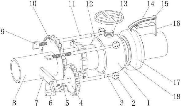
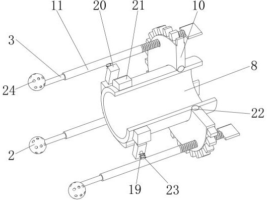
[0033] A valve with antifreeze function, such as Figure 1-4As shown, it includes a valve body 1 installed on the delivery pipe 8, the outer wall of the valve body 1 is embedded with a heating wire assembly, and the heating wire assembly includes a first heating wire 12 installed on the surface of the valve body 1 and an installation The second heating wire 13 at the rotation position of the valve stem in the valve body 1, the control mechanism for controlling the operation of the first heating wire 12 and the second heating wire 13 is installed on the delivery pipe 8, and the outer wall of the delivery pipe 8 is integrated Two spacer rings 18 are provided, and an air bag 17 is sleeved on the outside of the delivery pipe 8, and the air bag 17 is located between the two spacer rings 18. The control mechanism includes a shrapnel bracket 14, a support plate 15 and a mounting frame 16. One side of the outer wall of the shrapnel bracket 14 and the support plate 15 is installed on t...

Embodiment 2

[0044] A valve with antifreeze function, such as Figure 5 As shown, in order to facilitate the automatic control of antifreeze; this embodiment makes the following improvements on the basis of embodiment 1: the drive mechanism includes a motor 30, a connecting shaft 5 and a driving gear 4, and the connecting shaft 5 is installed on the The outer wall of one side of the delivery pipe 8, the driving gear 4 is fixed on the outer wall of one end of the connecting shaft 5 by screws, and the driving gear 4 is meshed with the driven gear 10; the motor 30 is fixed on the outer wall of the rotating shaft frame 7 by screws, and the The output end is rotatably connected to the outer wall of one end of the connecting shaft 5 through a coupling, and the two conductive plates 26 are connected to the control circuit of the motor 30 .

[0045] When this embodiment is in use, since the two conductive sheets 26 are connected to the motor 30, the deformation of the airbag 17 is used to control ...


PUM


Abstract

The invention discloses a valve with an anti-freezing function, and relates to the technical field of valve devices. The valve aims to improve the effect of automatic heating control. The valve specifically comprises a valve body installed on a conveying pipe, wherein an electric heating wire assembly is installed on the outer wall of the valve body in an embedded mode, the electric heating wire assembly comprises a first electric heating wire installed on the surface of the valve body and a second electric heating wire installed at the rotating position of a valve rod in the valve body, a control mechanism for controlling the first electric heating wire and the second electric heating wire to work is installed on the conveying pipe, and two limiting rings are integrally arranged on the circumferential outer wall of the conveying pipe. According to the valve, an air bag, a conductive strip, a conductive sheet and other structures are arranged, the capacity of thermal expansion and coldcontraction of the air bag can be utilized, so that the first electric heating wire and the second electric heating wire work to heat the valve body, moreover, due to the fact that the expansion andcontraction process of the air bag is relatively slow, the phenomenon that the conductive strip and the conductive sheet are repeatedly contacted and separated is avoided, and the working stability ofthe first electric heating wire and the second electric heating wire is guaranteed.

Description

technical field [0001] The invention relates to the technical field of valve devices, in particular to a valve with antifreeze function. Background technique [0002] A valve is a mechanical device that controls the flow rate and flow direction of the flowing fluid medium. The valve is a basic component in the pipeline system; during the pipeline transportation process, the transportation work is controlled through the valve according to the actual needs; due to the influence of the external environment, when When the temperature is too low, the valve may be frozen, which will affect the user's control of the valve; at present, antifreeze valves designed for this problem mostly use heating to prevent freezing, although a certain antifreezing effect has been achieved, but , the work of the heating mechanism cannot be controlled by itself according to the temperature, continuous heating leads to high energy consumption, and the antifreeze effect of intermittent heating cannot ...

Claims


Application Information

Patent Timeline
Patent Type & Authority Applications(China)
IPC IPC(8): F16K49/00F16K51/00F16L53/30H05B1/02H05B3/06H01H37/40
CPCF16K49/002F16K51/00F16L53/30H01H37/40H05B1/0208H05B3/06
Inventor 舒瑞
Owner 舒瑞
Why Eureka
Try Eureka