
Signal lamp color enhancement method and device and electronic equipment

A color enhancement, signal light technology, applied in the field of images, can solve problems such as abnormal images

Pending Publication Date: 2021-01-12
ZHEJIANG UNIVIEW TECH CO LTD
View PDF5 Cites 0 Cited by
  • Summary
  • Abstract
  • Description
  • Claims
  • Application Information

AI Technical Summary

Problems solved by technology

[0004] In view of this, the purpose of the present invention is to provide a signal light color enhancement method, device and electronic equipment, by performing fast, simple and efficient color enhancement processing on the collected images containing signal lights, in order to meet the requirements of higher timeliness Under the premise, solve the problem of abnormality in the images collected by the front-end equipment under special environmental conditions

Method used


Image

  • Signal lamp color enhancement method and device and electronic equipment
  • Signal lamp color enhancement method and device and electronic equipment
  • Signal lamp color enhancement method and device and electronic equipment

Examples


no. 1 example

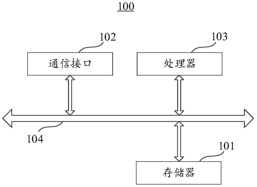
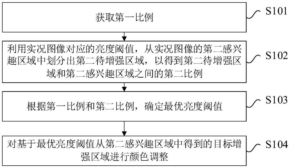
[0030] Please refer to figure 2 , figure 2 It shows that the signal light color enhancement method provided by the embodiment of the present invention is applied to the electronic device 100 . The above-mentioned signal light color enhancement method includes the following steps:

[0031] Step S101, acquiring a first ratio.

[0032] In the embodiment of the present invention, the first ratio may be a ratio between the first region to be enhanced and the first region of interest in the sample image. The above-mentioned first area to be enhanced is the bulb area of ​​the signal light in the sample image identified by using the preset model. The above-mentioned first region of interest is an image region including the first region to be enhanced. In the first region of interest, the first region to be enhanced is the foreground, and the other regions are the background.

[0033] The aforementioned first region to be enhanced and the first region of interest may be identifi...

no. 2 example

[0095] Please refer to Image 6 , Image 6 A signal light color enhancing device 200 provided by an embodiment of the present invention is shown. The above signal light color enhancement device 200 is applied to the electronic device 100 . Optionally, the signal light color enhancement device 200 includes: an acquisition module 201 , a division module 202 , a determination module 203 and a color enhancement module 204 .

[0096] The acquisition module 201 is configured to acquire the first ratio.

[0097] In the embodiment of the present invention, the above step S101 may be executed by the obtaining module 201 . Optionally, the first ratio includes a ratio between the first region to be enhanced and the first region of interest identified from the sample image by using a preset model.

[0098] The above division module 202 is configured to divide the second region to be enhanced from the second region of interest of the live image by using the brightness threshold corresp...


PUM


Abstract

The embodiment of the invention provides a signal lamp color enhancement method and device and electronic equipment, and relates to the technical field of images. The signal lamp color enhancement method comprises the following steps: acquiring a first proportion, wherein the first proportion comprises a proportion between a first to-be-enhanced region and a first region of interest recognized from the sample image by using a preset model; dividing a second region to be enhanced from a second region of interest of the live image by using a brightness threshold corresponding to the live image to obtain a second proportion between the second region to be enhanced and the second region of interest; determining an optimal brightness threshold value according to the first proportion and the second proportion; and performing color adjustment on a target enhancement region obtained from the second region of interest based on the optimal brightness threshold. Therefore, the position and the range of the bulb area in the live image can be quickly and accurately determined, and color enhancement can be carried out. The requirement of a user for image quality can be met, and the requirement of real-time data for timeliness can also be met.

Description

technical field [0001] The present invention relates to the field of image technology, in particular, to a signal light color enhancement method, device and electronic equipment. Background technique [0002] With the gradual development of the electronic police system, the electronic police system has become the main equipment for law enforcement officers to collect evidence of traffic violations. However, the front-end equipment of the electronic police system is usually distributed in an outdoor environment. Due to the influence of the installation position, angle or light conditions of the front-end equipment, the effect of the image directly collected by the front-end equipment is usually difficult to meet the user's requirements. For example, in the case of heavy fog or strong backlighting, the images containing signal lights are not only unclear, but also the color of the lights will be white or yellow, which will affect the effectiveness of illegal image materials to...

Claims


Application Information

Patent Timeline
Patent Type & Authority Applications(China)
IPC IPC(8): G06T5/00G06T7/90
CPCG06T5/00G06T7/90G06T2207/10004G06T2207/10024
Inventor 项晨晨项小胜肖乃瑶
Owner ZHEJIANG UNIVIEW TECH CO LTD
Learn More