An optical amplification transmission device and method applied to an optical fiber time transfer network

A time transfer and amplification device technology, applied in the field of optical transmission, can solve the problems of reducing device reliability and working life, switching or switching times (low life, occupying effective transmission time, etc.), to solve transmission problems, facilitate engineering applications, The effect of eliminating measurement errors

Active Publication Date: 2021-12-14
电信科学技术第五研究所有限公司
View PDF5 Cites 0 Cited by
  • Summary
  • Abstract
  • Description
  • Claims
  • Application Information

AI Technical Summary

Problems solved by technology

This method switches the forward and backward fiber channel connections through optical switching, so that both forward and backward light pass through the same optical amplifier, and the passing optical fiber links are the same, ensuring link symmetry to a large extent , but this method needs to switch the optical switch frequently according to the half-duplex signal transmission mechanism, and the switching or switching times of the optical switch (the life is low, the number of switching times is not more than 100,000 times) is limited, which will reduce the reliability of the device Sex and working life, not conducive to practical engineering applications
The switching noise of the optical switch will also be amplified by the optical amplifier, which will adversely affect the stable operation of the system. At the same time, the switching time of the optical switch will also occupy the effective transmission time

Method used


Image

  • An optical amplification transmission device and method applied to an optical fiber time transfer network
  • An optical amplification transmission device and method applied to an optical fiber time transfer network
  • An optical amplification transmission device and method applied to an optical fiber time transfer network

Examples


Embodiment Construction

[0034] The present invention will be further described below in conjunction with the accompanying drawings.

[0035] The technical solution of the present invention solves the following problems:

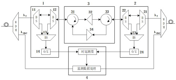
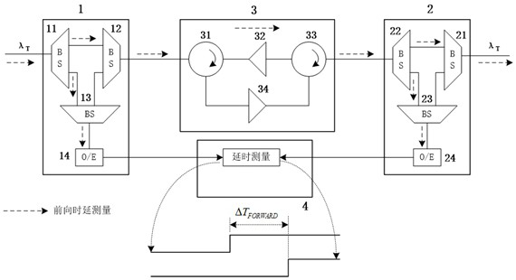
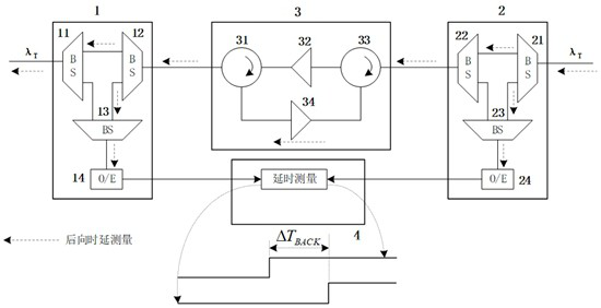
[0036] 1) Since the high-precision time transmission adopts single-fiber same-wavelength bidirectional transmission, it is necessary to amplify the forward and backward optical signals. In combination with actual network applications, the amplification nodes usually have different settings for the forward and backward optical amplification parameters. Therefore, it is necessary to separate the forward and backward optical signals from the single fiber, and use two amplifiers to amplify the forward and backward optical signals respectively, and have independent setting or adjustment to adapt to different networks environment and application requirements;

[0037] 2) Since different amplifiers are used in the forward and backward directions, the material characteristics and lengths o...


PUM


Abstract

The invention provides an optical amplification transmission device applied to an optical fiber time transfer network, comprising a first detection device, a second detection device, a bidirectional optical amplification device, and a time delay measurement device; the first detection device is connected with the bidirectional optical amplification device respectively 1. The time delay measurement device is connected to divide the optical signal transmitted into the first detection device into two paths, one path is connected to the bidirectional optical amplification device, and the other path is connected to the time delay measurement device through the photoelectric conversion device; the bidirectional optical amplification device is used to Two-way amplification of the optical signal; the second detection device is connected with the two-way optical amplification device and the time delay measurement device respectively; the time delay measurement device measures the signal time delay difference between the first detection device and the second detection device, and then according to the signal time delay Calculate the transmission error of the time signal through the optical amplification device, and transmit the transmission error data to the optical fiber time transfer device for calculation and processing of the time transfer signal, thereby improving the time transfer performance. The technical scheme of the invention can flexibly adjust the parameters of the amplifier according to the network planning and application, and is convenient for engineering application. This method has a wide range of applications and has application value.

Description

technical field [0001] The invention relates to the field of optical transmission, in particular to an optical amplification transmission device and method applied to an optical fiber time transfer network. Background technique [0002] The invention relates to that with the continuous development of communication, navigation, astronomical observation, electric power and transportation systems, and scientific research, the requirement for high-precision time transfer is getting higher and higher, and the demand is also stronger. At present, satellite-based timing technologies, such as satellite common view method and satellite two-way time comparison method, due to the interference of environmental factors on free space transmission links, the accuracy of time transfer can only reach the nanosecond level. With the continuous development of new technologies, especially the application of various distributed systems that are more dependent on time in the wide area, these time ...

Claims


Application Information

Patent Timeline
Patent Type & Authority Patents(China)
IPC IPC(8): H04B10/297H04B10/079H04J14/02
CPCH04B10/2971H04B10/0795H04J14/0216H04J14/0227
Inventor 何定高楚鹰军蒋鹰王茂凌胥骥谢平
Owner 电信科学技术第五研究所有限公司
Why Eureka
Try Eureka