Convenient-to-clean recovery treatment device for rare earth waste liquid
A technology that is convenient for cleaning and recycling. It can be used in separation methods, chemical instruments and methods, filtration and separation, etc. It can solve the problems of rare earth element loss, adhesion impurities, and rare earth resource loss, and achieve the effect of cleaning and optimizing the removal effect.
- Summary
- Abstract
- Description
- Claims
- Application Information
AI Technical Summary
Problems solved by technology
Method used
Image
Examples
Embodiment 1
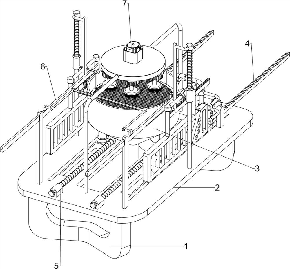
[0024] A convenient cleaning recovery treatment device for rare earth waste liquid, such as figure 1 As shown, it includes a base 1, a workbench 2, a material storage frame 3, a pushing mechanism 4, a moving mechanism 5 and a scraping mechanism 6. The base 1 is provided with a workbench 2, and the workbench 2 is provided with a push mechanism 4. A sliding mechanism 5 is provided in the middle of the table 2, a material storage frame 3 is provided on the mobile mechanism 5, and a scraping mechanism 6 is provided on the outside of the workbench 2.
[0025] First, pour the rare earth waste liquid into the storage frame 3, and then turn on the push mechanism 4, the operation of the push mechanism 4 will drive the operation of the moving mechanism 5, thereby driving the operation of the scraping mechanism 6, and the cleaning of the rare earth waste liquid can be realized After the cleaning is completed, close the push mechanism 4, and the stop of the push mechanism 4 will stop the ...
Embodiment 2
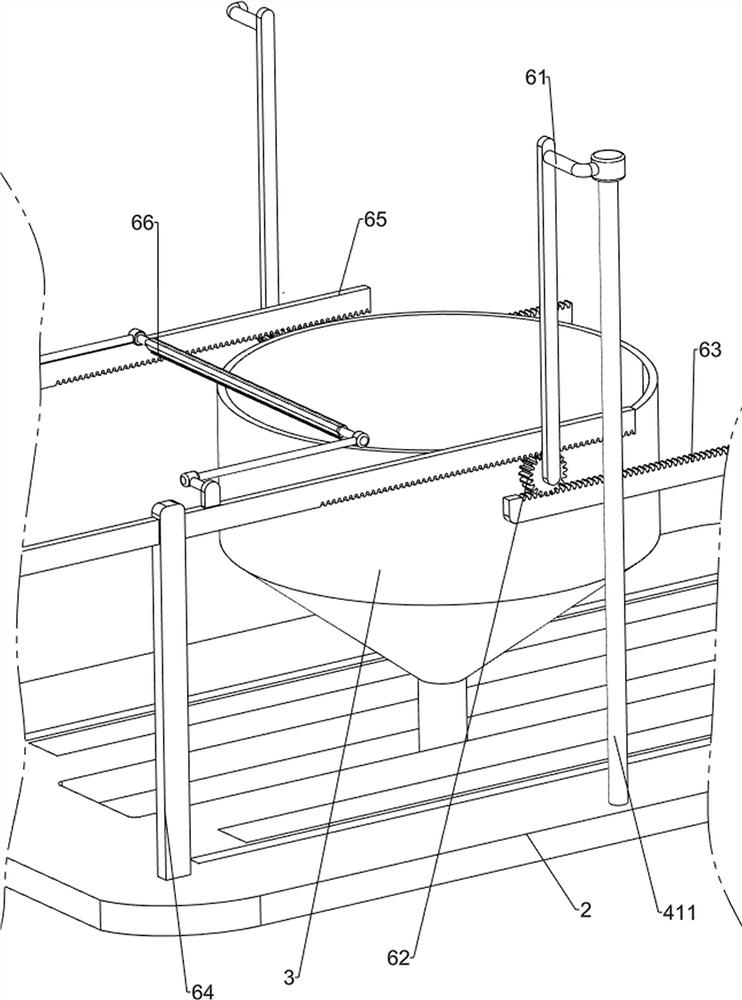
[0027] On the basis of Example 1, such as figure 1 , figure 2 , image 3 , Figure 4 As shown, the pushing mechanism 4 includes a mount 41, a first motor 42, a first bracket 43, a first L bar 44, a first rotating shaft 45, a first spur gear 46, a spur rack 47, a U-shaped bar 48, a small Wedge block 49, large wedge block 410, the first slide bar 411, the first sliding sleeve 412, the first spring 413 and filter screen 414, the left rear side on the workbench 2 is provided with mounting seat 41, and the mounting seat 41 is equipped with the first A motor 42, the output shaft of the first motor 42 is provided with the first rotating shaft 45, and the first rotating shaft 45 is provided with the first straight gear 46 symmetrically before and after, and the left front side on the workbench 2 is provided with the first support 43, the first support 43 is rotationally connected with the first rotating shaft 45, and the front and rear symmetrical sliding type on the right side of...
Embodiment 3
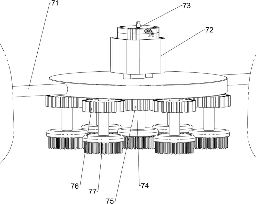
[0034] On the basis of Example 2, such as figure 1 , Figure 5 Shown, also include cleaning mechanism 7, be provided with cleaning mechanism 7 on the workbench 2, cleaning mechanism 7 includes second L bar 71, installation frame 72, second motor 73, second rotating shaft 74, large rack 75, A small rack 76 and a brush 77, a second L bar 71 is arranged symmetrically in the middle of the workbench 2, an installation frame 72 is arranged between the two second L bars 71 tops, and a second motor 73 is installed on the installation frame 72. The output shaft of the second motor 73 is provided with a second rotating shaft 74, the second rotating shaft 74 passes through the mounting frame 72 and is connected in rotation with it, the second rotating shaft 74 is provided with a large rack 75, and the bottom of the mounting frame 72 is uniformly rotated There are six brushes 77, and the brushes 77 are all provided with a small rack 76, and the small rack 76 is engaged with the large rac...
PUM
 Abstract
Description
Claims
Application Information
 - R&D
- Intellectual Property
- Life Sciences
- Materials
- Tech Scout
- Unparalleled Data Quality
- Higher Quality Content
- 60% Fewer Hallucinations
Browse by: Latest US Patents, China's latest patents, Technical Efficacy Thesaurus, Application Domain, Technology Topic, Popular Technical Reports.
© 2025 PatSnap. All rights reserved.Legal|Privacy policy|Modern Slavery Act Transparency Statement|Sitemap|About US| Contact US: help@patsnap.com


