Air compressor filter element cleaning method

An air compressor and filter element technology, which is applied in the field of compressor equipment, can solve the problem of rapid temperature rise of the filter element, and achieve the effects of preventing rapid temperature rise, simple structure, and improving work efficiency

Inactive Publication Date: 2021-01-15
湖州师范学院求真学院
View PDF6 Cites 3 Cited by
  • Summary
  • Abstract
  • Description
  • Claims
  • Application Information

AI Technical Summary

Problems solved by technology

[0005] In view of the above problems, the present invention provides a method for cleaning the filter element of an air compressor, wherein the driving assembly first drives two sets of mounting sleeves and the filter element to rotate 180°, the rotating plate and the arc plate rotate accordingly, and the filter element is installed during the rotation process. Vibration in the sleeve, through the rotation of the control block, the outlet pipe of the air compressor inflates the cleaning assembly and supplies air to the air intake pipe of the air compressor. After the rotation is complete, the cleaning assembly reversely inflates and cleans the filter element, and the driving assembly drives the rotating plate It rotates independently and drives the corresponding piston rod to move, so that the arc-shaped plate facing the air inlet can absorb dust, and the arc-shaped plate facing the air outlet can blow air to cool down the air intake station, which solves the problem of the temperature of the working station of the filter element in the prior art. Too high a technical problem that causes the filter element to heat up quickly

Method used


Image

  • Air compressor filter element cleaning method
  • Air compressor filter element cleaning method
  • Air compressor filter element cleaning method

Examples


Embodiment 1

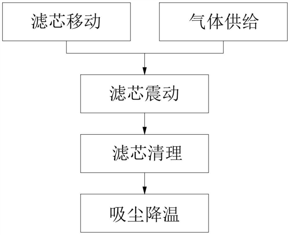
[0047] Such as figure 1 Shown, a kind of air compressor filter element cleaning method comprises the following steps:

[0048] Step 1: The filter element moves, the driving assembly 91 drives the rotating shaft 131 to rotate, and the rotating shaft 131 drives two sets of installation sleeves 151 to rotate so that the used filter element 14 and the clean filter element 14 are separated from the air outlet 7 and the air inlet respectively 6 and close the air outlet 7 and the air inlet 6;

[0049] Step 2: Gas supply is carried out synchronously with step 1. The rotating shaft 131 drives the rotating block 534 arranged in the control box 532 to rotate through the gear transmission assembly 52, and the air compressor outlet pipe and the air compressor inlet pipe and the cleaning assembly 51 are communicated, and the air compressor outlet pipeline carries out gas replenishment to the air compressor inlet pipeline, and the cleaning assembly 51 is inflated;

[0050] Step 3: The filt...

Embodiment 2

[0063] The present invention also provides an air compressor filter element cleaning system:

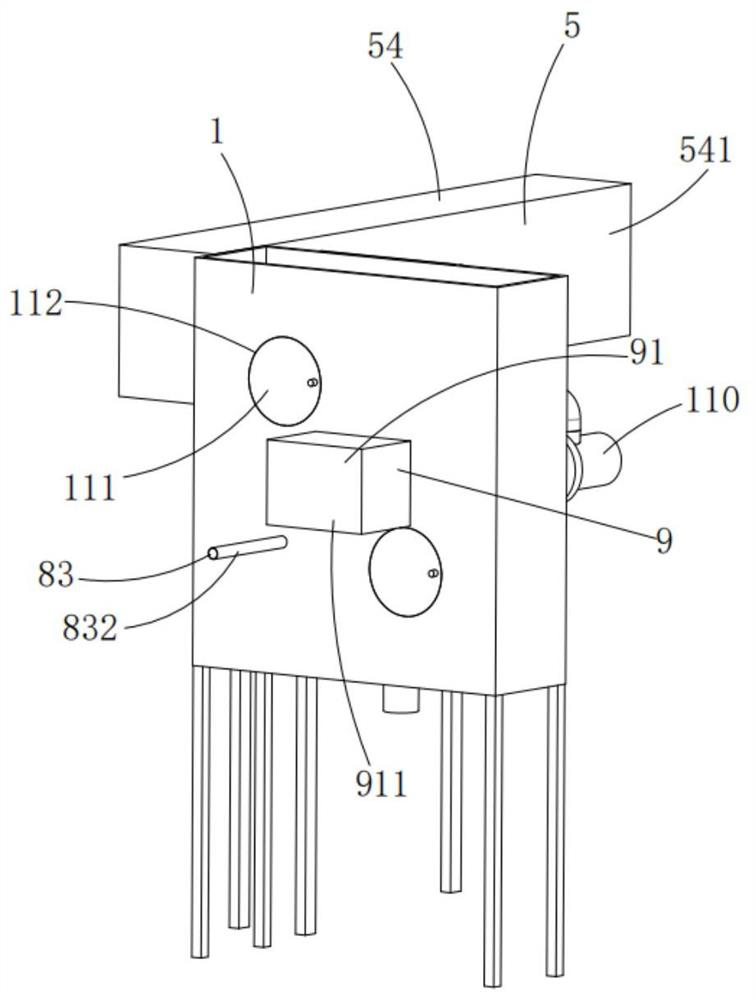
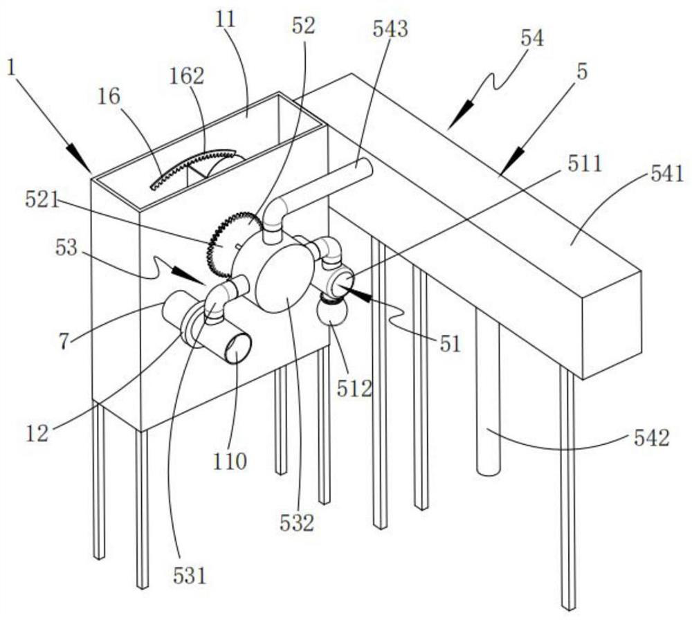
[0064] Such as Figure 2 to Figure 5 As shown, an air compressor filter element cleaning system includes:

[0065] Installation equipment 1, the installation equipment 1 includes a box body 11 provided with an air inlet 6 and an air outlet 7, a rotating assembly 13 installed in the box body 11, symmetrically and fixedly installed on the rotating assembly 13, and Two sets of installation assemblies 15 for installing the filter element 14 and a limit assembly 16 arranged corresponding to the installation assemblies 15 and driving the installation assemblies 15 to reciprocate and meridian; the air outlet 7 is connected to the air compressor air intake duct communication; the rotating assembly 13 rotates and drives two groups of the mounting assemblies 15 to align with the air inlet 6 and the air outlet 7 alternately;

[0066] Cleaning equipment 5, the cleaning equipment 5 includes a c...


PUM


Abstract

The invention relates to an air compressor filter element cleaning method which comprises the following steps that 1, a filter element moves, a driving assembly drives a rotating shaft to rotate, theused filter element and a clean filter element rotate away from an air outlet and an air inlet respectively, and the air outlet and the air inlet are closed; 2, gas supply, wherein a rotating block rotates to enable a gas outlet pipeline of the air compressor to supply gas to a gas inlet pipeline inlet and cleaning assembly of the air compressor; 3, vibrating the filter element, and enabling the used filter element to rotate and move in the mounting sleeve along with the rotation of the mounting sleeve; 4, cleaning the filter element, respectively aligning the used filter element and the cleanfilter element with the air inlet and the air outlet, and carrying out reverse blowing cleaning on the used filter element by the cleaning assembly; 5, dust collection and cooling are conducted, specifically, a driving assembly independently drives a rotating plate to rotate, then a driving lever and a corresponding piston column are driven to move, and then an arc-shaped plate located on one side of an air inlet conducts dust collection; and the arc plate located at one side of the air oulet blows air for cooling down. According to the method, the cooling effect is good.

Description

technical field [0001] The invention relates to compressor equipment, in particular to a method for cleaning an air compressor filter element. Background technique [0002] When the air compressor is working, external air enters the air compressor through the air filter element for compression, and the temperature at the air inlet will rise during use, which will affect the use effect of the filter element, and the impurities attached to the air filter element will also affect The efficiency of the air compressor. [0003] The invention patent with the Chinese patent application number CN201710092726.6 discloses an air filter element cleaning device, which belongs to the technical field of filter element cleaning equipment. The valve is connected with a first plunger intake pipe, a first plunger exhaust pipe, a second plunger intake pipe and a second plunger exhaust pipe, the first plunger intake pipe is provided with a first intake switch valve, The first plunger exhaust ...

Claims


Application Information

Patent Timeline
IPC IPC(8): B01D46/24B01D46/00F04B39/16
CPCB01D46/2411F04B39/16B01D46/90B01D46/71
Inventor 祝鹏飞祝守新
Owner 湖州师范学院求真学院
Why Eureka
Try Eureka