Treatment equipment for inclined surface of metal material
A technology for inclined surfaces and metal materials, applied in metal processing equipment, grinding/polishing equipment, grinding machines, etc., to achieve the effects of adjustment, easy collection, and safety protection
- Summary
- Abstract
- Description
- Claims
- Application Information
AI Technical Summary
Problems solved by technology
Method used
Image
Examples
Embodiment 1
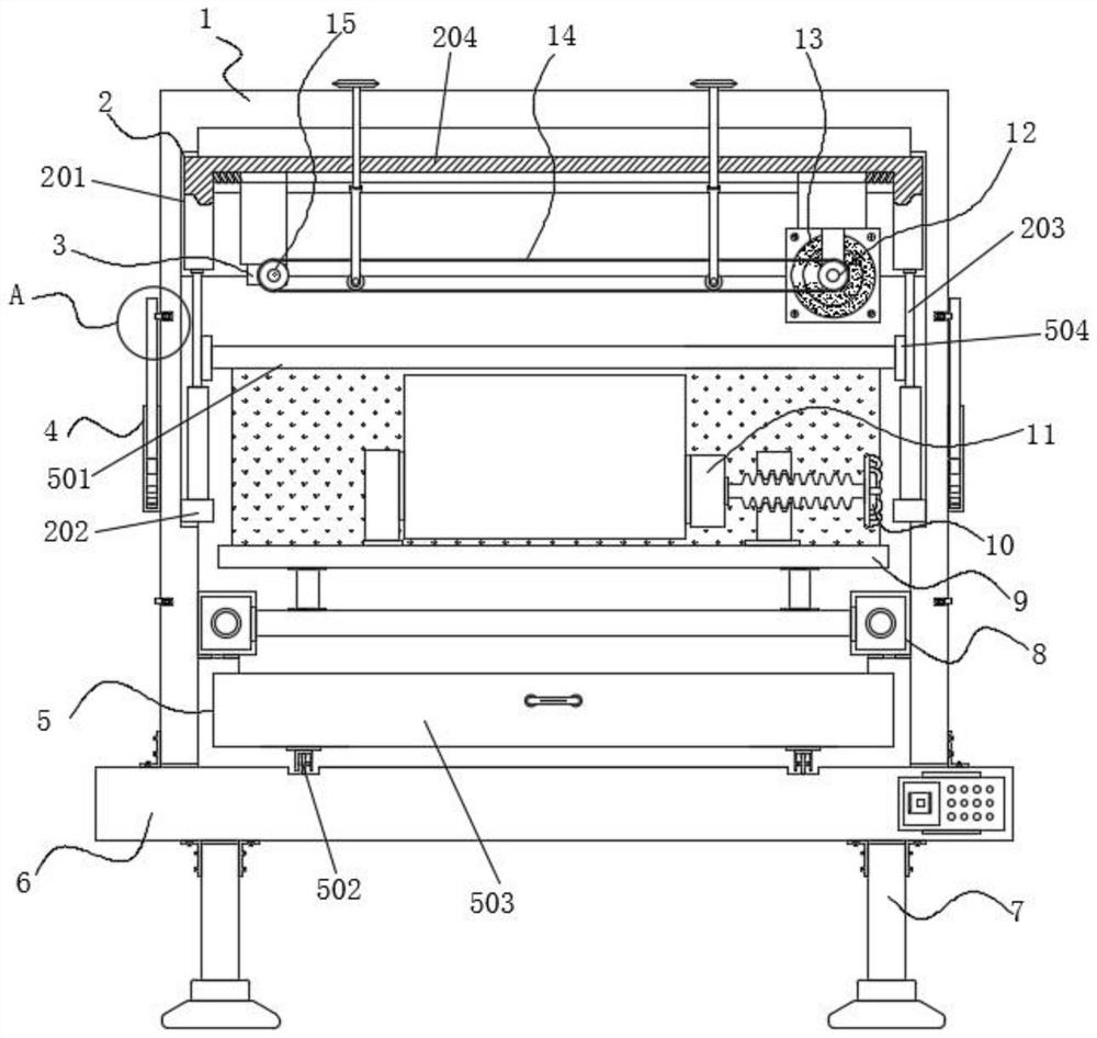
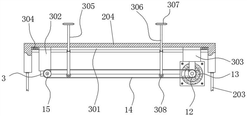
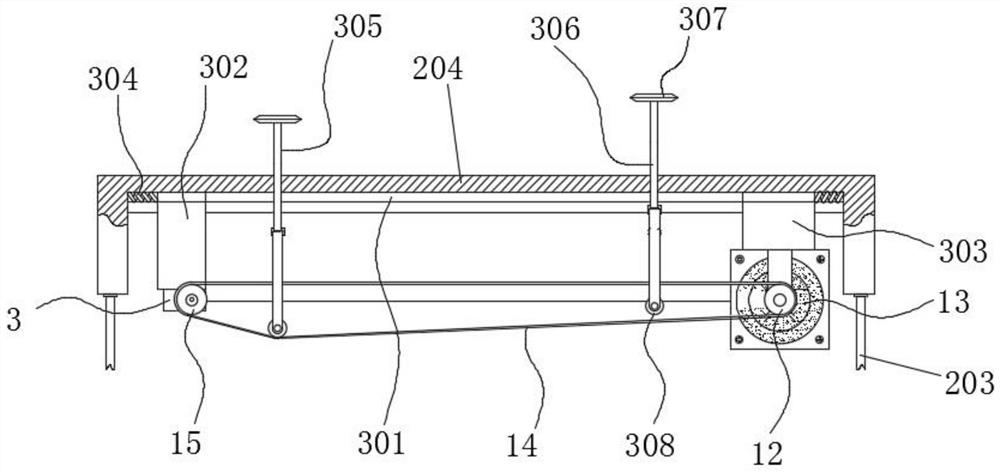
[0039] Example 1: See Figure 1-8 , a metal material inclined surface treatment equipment, comprising a frame body 1 and a base 6, the bottom of the base 6 is fixedly connected with a support foot 7, the top of the base 6 is fixedly connected with a frame body 1, and the two sides outside the frame body 1 are provided with lifting Structure 4, a cleaning structure 5 is provided on the top of the base 6, a telescopic mechanism 2 is provided at the middle of both sides inside the frame body 1, and a feeding mechanism 8 is fixedly connected to the bottom ends of both sides inside the frame body 1, and the feeding mechanism 8 A movable seat 9 is fixedly connected to one side of the movable seat 9, and a clamping mechanism is arranged on the top of the movable seat 9;
[0040] The telescopic mechanism 2 is composed of a fixed groove 201, a fixed block 202, an electric telescopic rod 203 and a support frame 204. The fixed groove 201 is arranged at the middle position of both sides i...
Embodiment 2
[0043] Example 2; see Figure 1-8 , a metal material inclined surface treatment equipment, the clamping mechanism also includes a first support seat 16, the first support seat 16 is arranged on one side of the top of the movable seat 9, and the top of the first support seat 16 is provided with a second screw rod 17, One side of the second screw rod 17 is fixedly connected with the knob 10, the other side of the second screw rod 17 is fixedly connected with the second movable block 11, and the other side of the movable seat 9 top is fixedly connected with the second support seat 18;
[0044] Specifically, such as figure 1 with Figure 5 As shown, the material to be processed is placed on the top of the movable seat 9, and by rotating the knob 10, the second screw rod 17 rotates inside the first support seat 16 to drive the second movable block 11 to move to the left, reducing the second movable block. The distance between the block 11 and the second support seat 18 clamps and...
Embodiment 3
[0045] Embodiment 3: The lifting structure 4 is composed of a door body 401, a fixed gear 402, a handle 403, a first movable block 404, a support spring 405 and a reserved groove 406. The door body 401 is arranged at the bottom of one end of the frame body 1, and the door body 401 One end of the one-end frame body 1 is provided with a reserved groove 406, one side of the reserved groove 406 is fixedly understood to have a supporting spring 405, and the other side of the supporting spring 405 is fixedly connected with a first movable block 404, and the two sides of the door body 401 One end is provided with a fixed gear 402, one side of the fixed gear 402 is fixedly connected with a handle 403, and one end on both sides of the door body 401 is provided with a rack, the door body 401 and the fixed gear 402 form a meshing structure, and the first movable block 404 The front section and the rear end are provided with chamfers;
[0046] Specifically, such as figure 1 , Image 6 w...
PUM
 Abstract
Description
Claims
Application Information
 - R&D
- Intellectual Property
- Life Sciences
- Materials
- Tech Scout
- Unparalleled Data Quality
- Higher Quality Content
- 60% Fewer Hallucinations
Browse by: Latest US Patents, China's latest patents, Technical Efficacy Thesaurus, Application Domain, Technology Topic, Popular Technical Reports.
© 2025 PatSnap. All rights reserved.Legal|Privacy policy|Modern Slavery Act Transparency Statement|Sitemap|About US| Contact US: help@patsnap.com


