Glass suction cup mechanical arm

A manipulator and suction cup technology, applied in the direction of manipulators, conveyor objects, furnaces, etc., can solve the problems of inability to meet the special design requirements of customers, the manipulator cannot adjust the spacing of suction cups, and is not suitable for handling shaped glass plates, etc., to achieve stable, reliable and practical transportation. Strong, easy-to-use effects

Pending Publication Date: 2021-01-15
河南金禾智能装备有限公司
View PDF0 Cites 2 Cited by
  • Summary
  • Abstract
  • Description
  • Claims
  • Application Information

AI Technical Summary

Problems solved by technology

[0005] Based on the above problems, the object of the present invention is to provide a glass suction cup manipulator, which is used to solve the problem that the manipulator in the prior art cannot adjust the distance between the suction cups, so it is not suitable for handling glass plates with irregular shapes, and thus cannot meet the special design requirements of customers.

Method used


Image

  • Glass suction cup mechanical arm
  • Glass suction cup mechanical arm
  • Glass suction cup mechanical arm

Examples


Embodiment 1

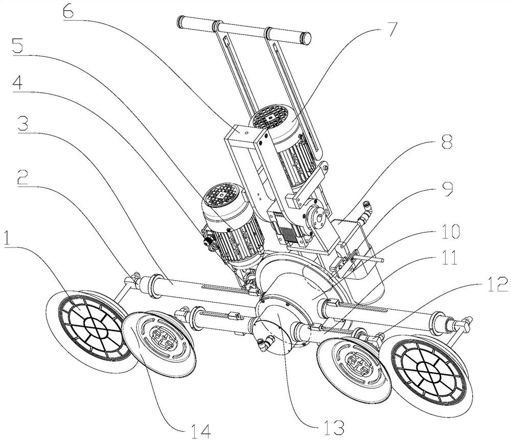
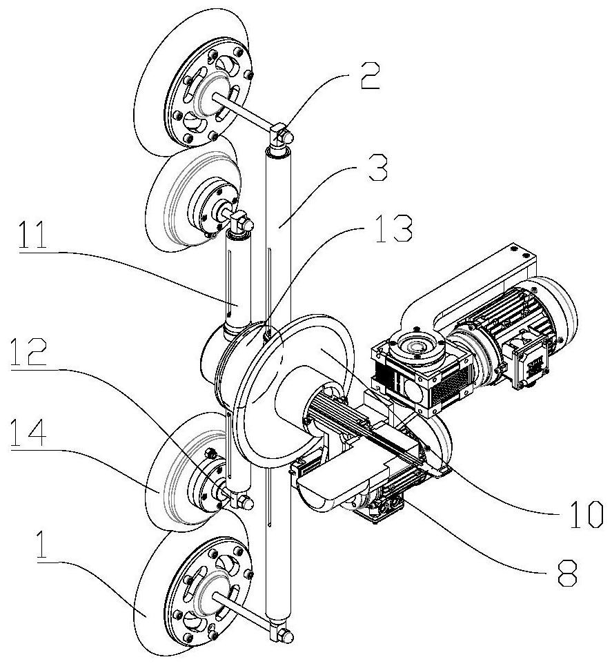
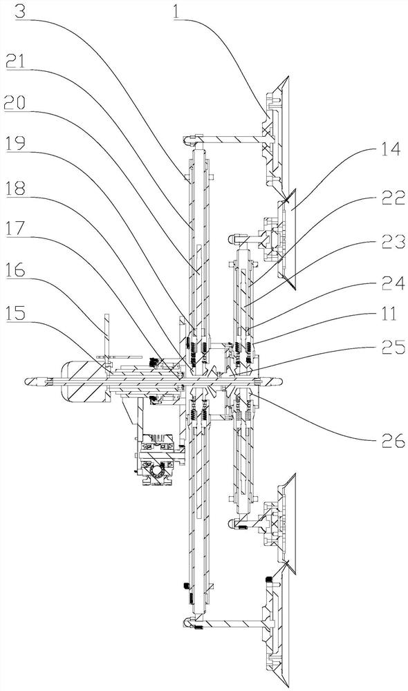
[0030] Such as Figure 1-6 As shown, a glass suction cup manipulator includes a front suction cup frame main body 13, a rear suction cup frame main body 10 and a suction cup adjustment shaft 17, and the suction cup adjustment shaft 17 passes through the front suction cup frame main body 13, the rear suction cup frame main body 10, and the front suction cup frame main body 13, a plurality of front fixed sleeve rods 11 are installed, and the front telescopic rod 12 and the front adjustment mechanism connected to each other are installed in the front fixed sleeve rod 11. The end of the front telescopic rod 12 is equipped with a front suction cup 14, and the rear suction cup holder main body 10 A plurality of rear fixed sleeve rods 3 are installed on the rear fixed sleeve rod 3, and the rear telescopic rod 2 and the rear adjustment mechanism connected to each other are installed in the rear fixed sleeve rod 3. The end of the rear telescopic rod 2 is equipped with a rear suction cup...

Embodiment 2

[0039] Such as Figure 1-6 As shown, on the basis of the above-mentioned embodiment 1, this embodiment provides a preferred structure that can facilitate the removal of the suction cup manipulator, that is, it also includes a corner reducer 5, the input end of the corner reducer 5 is connected to a corner motor, and the output end Be connected with rotating shaft, and rotating shaft is connected with sucker frame boom 6. When transporting the placed glass plates, the suction cup holder arm 6 is connected with the lifting device. When the space position of the suction cup holder arm 6 needs to be changed, the corner motor is operated to rotate by operating the external controller, and the corner motor drives the corner reducer 5 Operation, the corner reducer 5 drives the rotating shaft to rotate again, and the rotating shaft drives the suction cup hanger arm 6 to rotate again, so that the overall structure of the sucker hanger arm can be adjusted to be placed flat or in a cubic...

Embodiment 3

[0042] Such as Figure 1-6 As shown, on the basis of the above-mentioned embodiments 1 and 2, this embodiment provides a preferred structure that can make the relative rotation between the front suction cup 14 and the rear suction cup 1, that is, it also includes the rotation speed reducer 7, and the input end of the rotation speed reducer 7 A rotary motor is connected, the output end is connected with an output shaft, and a rotary gear 4 is installed on the output shaft, and the rear end of the rear sucker frame main body 10 is equipped with 4 turns of the rotary gear meshed with the rotary gear 4 . When it is necessary to change the angle of the front sucker 14 and the rear sucker 1 in space, the rotation of the rotary motor can be controlled by an external controller, and the rotary motor drives the rotary reducer 7 and the output shaft to rotate in turn, and the output shaft drives the rotary gear 4 to rotate again. The rotating gear 4 drives the rotating ring gear 9 to ro...


PUM


Abstract

The invention relates to the technical field of mechanical arms, in particular to a glass suction cup mechanical arm. The glass suction cup mechanical arm is used for solving the problems that a mechanical arm in the prior art cannot adjust the distance between suction cups, consequently, the mechanical arm is not suitable for carrying glass plates in irregular shapes, and then special design requirements of customers cannot be met. The glass suction cup mechanical arm comprises a front suction cup frame body, a rear suction cup frame body and a suction cup adjusting shaft. Multiple front fixed sleeve rods are installed on the front suction cup frame body, front telescopic rods and front adjusting mechanisms which are connected with one another are installed in the front fixed sleeve rods,and front suction cups are installed at the ends of the front telescopic rods. Multiple rear fixed sleeve rods are installed on the rear suction cup frame body, rear telescopic rods and rear adjusting mechanisms which are connected with one another are installed in the rear fixed sleeve rods, rear suction cups are installed at the ends of the rear telescopic rods, and a power mechanism is installed on suction cup adjusting shaft. By means of the technical scheme, the glass suction cup mechanical arm can be suitable for carrying glass plates in irregular shapes, and therefore special design requirements of customers can be met.

Description

technical field [0001] The invention relates to the technical field of suction cup manipulators, in particular to a glass suction cup manipulator. Background technique [0002] Glass is an amorphous inorganic non-metallic material. It is generally made of various inorganic minerals such as quartz sand, borax, boric acid, barite, barium carbonate, limestone, feldspar, soda ash, etc. as the main raw material, and a small amount of auxiliary raw materials. Its main components are silica and other oxides. Glass is widely used in various buildings. Glass needs to be transported in construction sites or workshops. In order to improve the efficiency of glass transport, corresponding glass transport is required. manipulator. [0003] The manipulator for transferring glass in the prior art includes a column, and also includes a support arm that is rotatably arranged on the column. A vertical cylinder is provided for sliding on the support arm. There is a suction cup frame for absor...

Claims


Application Information

Patent Timeline
Patent Type & Authority Applications(China)
IPC IPC(8): B25J15/06B65G49/06
CPCB25J15/0616B65G49/06
Inventor 王继远郭卫锋
Owner 河南金禾智能装备有限公司
Why Eureka
Try Eureka