Compression molding method of carbon fiber automobile chassis part

A technology of compression molding and automobile chassis, which is applied in the field of carbon fiber automobile chassis compression molding, can solve the problems of high cost, limited weight reduction effect, complicated process, etc., and achieve the effects of enhancing mechanical properties, reducing density, and reducing production costs

Inactive Publication Date: 2021-01-15
HUNAN JINGZHENG EQUIP MFG
View PDF2 Cites 0 Cited by
  • Summary
  • Abstract
  • Description
  • Claims
  • Application Information

AI Technical Summary

Problems solved by technology

At present, most of the conforming materials are made of steel, which has a limited weight reduction effect, and the manufacture of conforming plates is usually done by molding the parts first, and then pouring, the process is complicated and the cost is high

Method used


Image

  • Compression molding method of carbon fiber automobile chassis part
  • Compression molding method of carbon fiber automobile chassis part

Examples


Embodiment Construction

[0016] The present invention will be further described below in conjunction with the accompanying drawings.

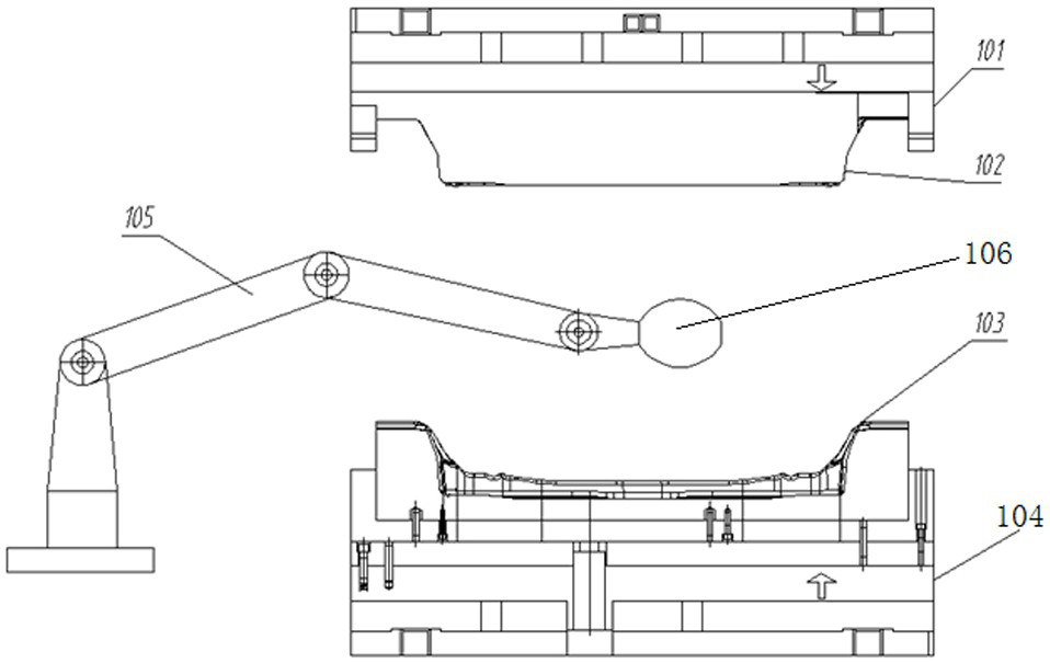
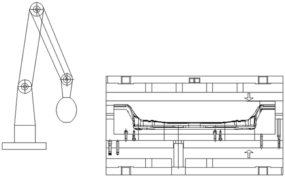
[0017] Such as figure 1 , 2 As shown, the compression molding die that the present invention adopts comprises the upper mold cavity 102 that has air hole and pouring hole, is provided with the upper mold base 101 of guide plate, has the lower mold cavity 103 of air hole, has the lower mold base 104 of guide groove The upper mold cavity 102 and the upper mold base 101 are fixedly connected to form an upper mold, and the lower mold cavity 103 and the lower mold base 104 are fixedly connected to form a lower mold;

[0018] The present invention comprises the steps:

[0019] 1) Fix the upper mold on the upper slider of the hydraulic equipment, fix the lower mold on the lower workbench of the hydraulic equipment, cut two pieces of carbon fiber cloth, and spread the two pieces of carbon fiber cloth on the upper mold cavity and the lower mold cavity respectively , and then...


PUM


Abstract

The invention discloses a compression molding method of a carbon fiber automobile chassis part. The method comprises the following steps: (1) an upper die and a lower die are respectively fixed on anupper sliding block and a lower workbench of oil pressure equipment, and an upper die cavity and a lower die cavity are respectively paved with two pieces of carbon fiber cloth, so that carbon fibersare completely adsorbed on the upper die cavity and the lower die cavity; (2) the upper die cavity and the lower die cavity are preheated; (3) the upper die is pushed to move towards the lower die byan upper sliding block of the oil pressure equipment, the upper die moves downwards to a fixed position under the action of an upper die guide plate and a lower die guide groove, a cavity gap definedby the upper die cavity and the lower die cavity is vacuumized, and a resin material is poured into the cavity gap defined by the upper die cavity and the lower die cavity; and (4) the upper die is pushed to move downwards through the upper sliding block of the oil pressure equipment to perform die-casting forming on the part. The process is simple, the part is formed in place in one step, the steps of plate shearing, stamping, forming and the like are omitted, the production cost is reduced, the mechanical performance of a product is greatly enhanced, and the density of workpieces with the same thickness is reduced.

Description

technical field [0001] The invention belongs to the technical field of carbon fiber profile forming, and in particular relates to a press forming method for a carbon fiber automobile chassis part. Background technique [0002] At present, remarkable achievements have been made at home and abroad in the use of composite materials with excellent performance, light weight and high strength to realize the lightweight of automobiles. Carbon fiber composite materials have lightweight characteristics and sufficient strength and stiffness. The lightest material for main structures such as the chassis and chassis. At present, most of the conforming materials are made of steel, which has a limited weight reduction effect, and the manufacture of conforming plates is usually done by molding the parts first, and then pouring, the process is complicated and the cost is high. Contents of the invention [0003] In order to solve the above technical problems, the present invention provide...

Claims


Application Information

Patent Timeline
Patent Type & Authority Applications(China)
IPC IPC(8): B29C70/34B29C70/54B29C35/08
CPCB29C70/342B29C70/54B29C35/0805B29C2035/0822
Inventor 赵烨张思遥李天虹赵子仁卢旺唐建光
Owner HUNAN JINGZHENG EQUIP MFG
Why Eureka
Try Eureka