Sealing machine for can production based on positioning mechanism

A positioning mechanism and sealing machine technology, applied in the direction of flanged bottle caps, etc., can solve problems such as inability to fit the surface of the can, danger, and cracking of the can, and achieve the effect of protecting the surface of the can and facilitating reset work

Active Publication Date: 2022-03-25
湖南芝麻官农业科技有限公司
View PDF6 Cites 0 Cited by
  • Summary
  • Abstract
  • Description
  • Claims
  • Application Information

AI Technical Summary

Problems solved by technology

[0002] The existing seaming machines basically only have the function of capping. Specifically, the synchronous positioning of metal round cans and round caps is realized through a group of double-layer turntables that can rotate synchronously. When the turntables stop, use the " "Lid Separator" puts the round cap into the lid support turntable on the upper floor, and the round cans to be sealed are sent to the can positioning turntable on the lower floor by conveyor belts and other equipment; then the central shaft drives the upper and lower turntables to rotate synchronously, and the The caps are sent to the sealing station synchronously, and the rotation is stopped, and finally the capping work is carried out, but the positioning mechanism of the existing sealing machine is not fixed, and the fixed splint cannot fit the surface of the can when it is clamping the can, resulting The seal is misplaced, and in severe cases, the can may break and be dangerous. Therefore, a new positioning mechanism for the sealing machine is needed to improve the deficiencies of the existing technology

Method used


Image

  • Sealing machine for can production based on positioning mechanism
  • Sealing machine for can production based on positioning mechanism
  • Sealing machine for can production based on positioning mechanism

Examples


Embodiment 1

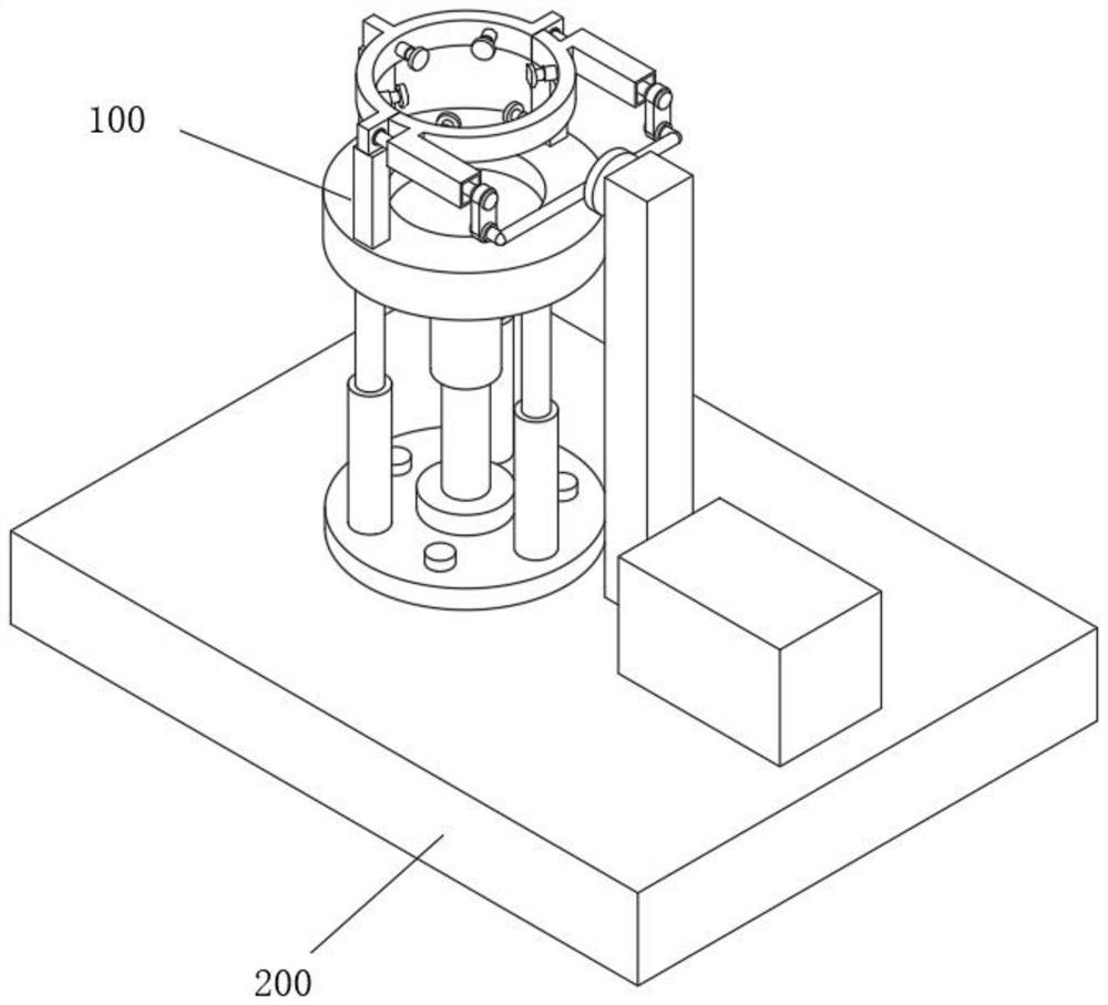
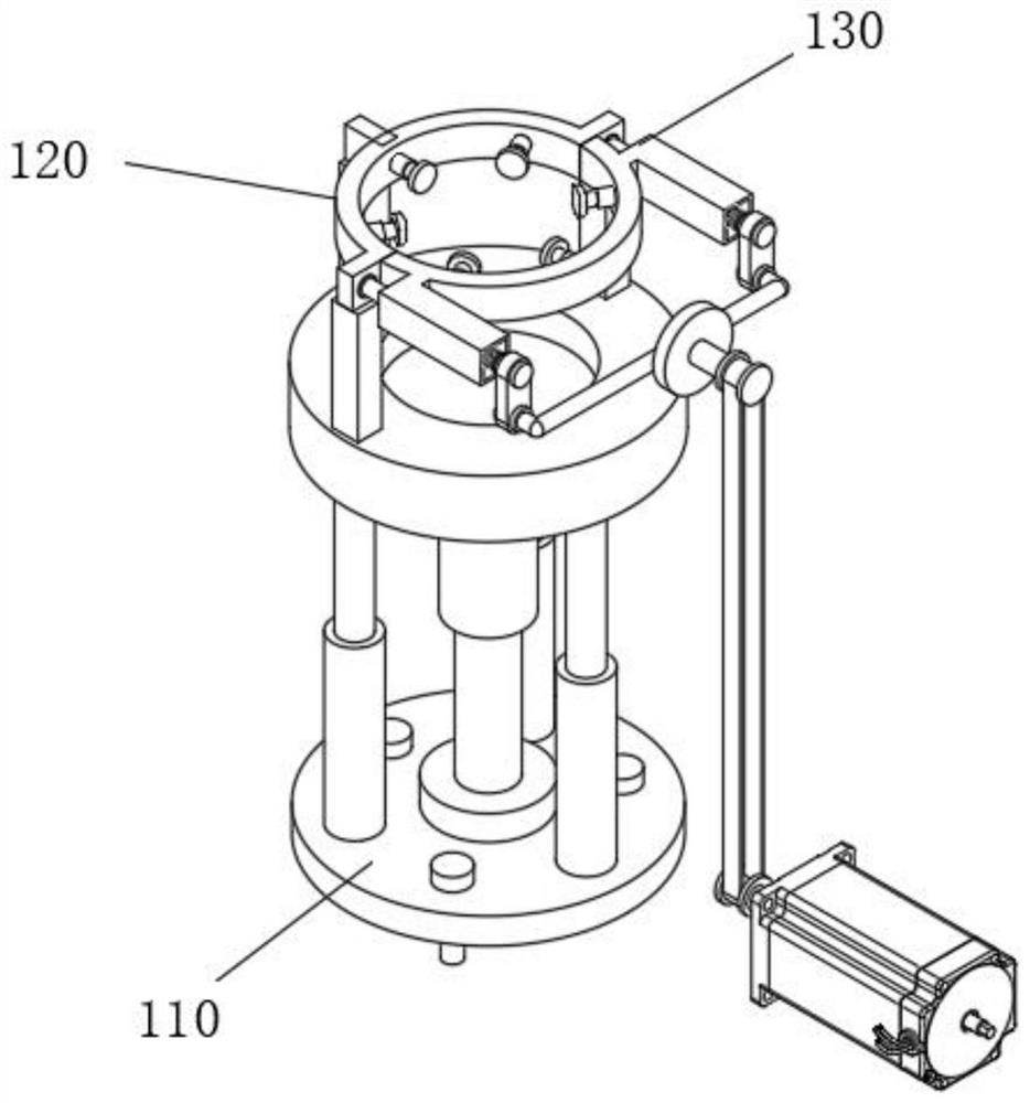
[0057] see Figure 1-Figure 12 As shown, the present embodiment provides a sealing machine for can production based on a positioning mechanism, including an operating platform 200 and a positioning device 100 installed above the operating platform 200, and the positioning device 100 at least includes:

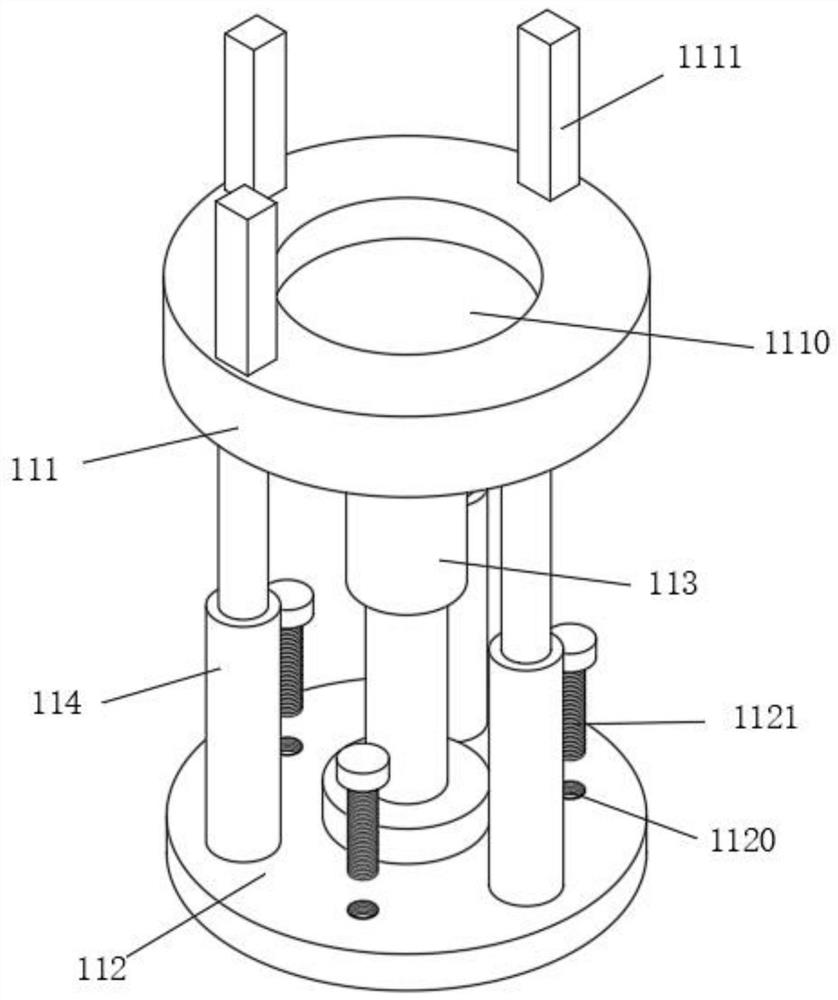
[0058] The supporting device 110, the supporting device 110 includes a fixed seat 111 and a base 112 connected below the fixed seat 111, the upper surface of the fixed seat 111 is provided with a fixed groove 1110, and the upper surface of the fixed seat 111 is located around the fixed groove 1110 and is provided with a support rod 1111 , the bottom end of the fixed seat 111 is fixedly equipped with a hydraulic rod 113, the hydraulic rod preferably adopts a piston type hydraulic rod, and its working principle is as known to those skilled in the art, with gas and liquid as the working medium, composed of pressure tubes, pistons, Composed of a piston rod and multiple connectors, ...


PUM


Abstract

The invention relates to the technical field of sealing machines, in particular to a sealing machine for can production based on a positioning mechanism. It includes an operating platform and a positioning device installed above the operating platform. In the sealing machine for can production based on the positioning mechanism, the cans are clamped by the fixed clamping block and the moving clamping block, and the screw is used to change the fixed clamping block. The distance between the clamping block and the moving clamping block is used to deal with cans of different specifications, and at the same time, the tightness of the clamping can be changed. Through the operation of the motor, the coaxial rotating rod drives the two screw rods to rotate at the same time, avoiding manual operation errors. As a result of equipment damage, the set close-fitting device plays a role in protecting the surface of the can. Through the sliding of the sliding cavity and the sliding block, the expansion and contraction function of the bonding piece can be realized, which is convenient to deal with cans of different specifications. At the same time, the set spring can , to facilitate the reset work of the lamination sheet.

Description

technical field [0001] The invention relates to the technical field of sealing machines, in particular to a sealing machine for can production based on a positioning mechanism. Background technique [0002] The existing seaming machines basically only have the function of capping. Specifically, the synchronous positioning of metal round cans and round caps is realized through a group of double-layer turntables that can rotate synchronously. When the turntables stop, use the " "Lid Separator" puts the round cap into the lid support turntable on the upper floor, and the round cans to be sealed are sent to the can positioning turntable on the lower floor by conveyor belts and other equipment; then the central shaft drives the upper and lower turntables to rotate synchronously, and the The caps are sent to the sealing station synchronously, and the rotation is stopped, and finally the capping work is carried out, but the positioning mechanism of the existing sealing machine is n...

Claims


Application Information

Patent Timeline
Patent Type & Authority Patents(China)
IPC IPC(8): B67B3/02
CPCB67B3/02
Inventor 宋阳力代泳波
Owner 湖南芝麻官农业科技有限公司
Why Eureka
Try Eureka