Eureka AIR delivers breakthrough ideas for toughest innovation challenges, trusted by R&D personnel around the world.

Steel bar fixing device for construction industry

A fixing device and technology in the construction industry, which is applied in construction, building structure, processing of building materials, etc., can solve the problems of inability to apply steel bars of different outer diameters, complicated processes, etc., and achieve the effect of solving the unsatisfactory production effect.

Inactive Publication Date: 2021-01-15
蒋俊学
View PDF5 Cites 0 Cited by
  • Summary
  • Abstract
  • Description
  • Claims
  • Application Information

AI Technical Summary

Problems solved by technology

[0002] The aperture reinforcement cage made in the construction industry is a cage-shaped reinforcement frame formed by using steel bars of the same diameter and binding them together by winding steel bars according to a certain outer diameter requirement; it is commonly used in steel-concrete structures, pouring, reinforced cement piles, etc. The reinforcement cage is the skeleton, which is filled or poured with the corresponding grade of concrete according to the prescribed process to solidify the fluid and improve the strength; however, most of the reinforcement cages are manually surrounded by reinforcements into a cage shape when they are initially fixed. end fixing, such a process is more complicated, and some devices that can pre-fix the steel bars are not suitable for steel bars with different outer diameters, and the use has limitations

Method used


Image

  • Steel bar fixing device for construction industry
  • Steel bar fixing device for construction industry
  • Steel bar fixing device for construction industry

Examples


Embodiment Construction

[0022] The following embodiments will describe the present invention in detail with reference to the drawings. In the drawings or descriptions, similar or identical parts use the same symbols, and in practical applications, the shape, thickness or height of each component can be enlarged or reduced. The various embodiments listed in the present invention are only used to illustrate the present invention, and are not intended to limit the scope of the present invention. Any obvious modifications or changes made to the present invention do not depart from the spirit and scope of the present invention.

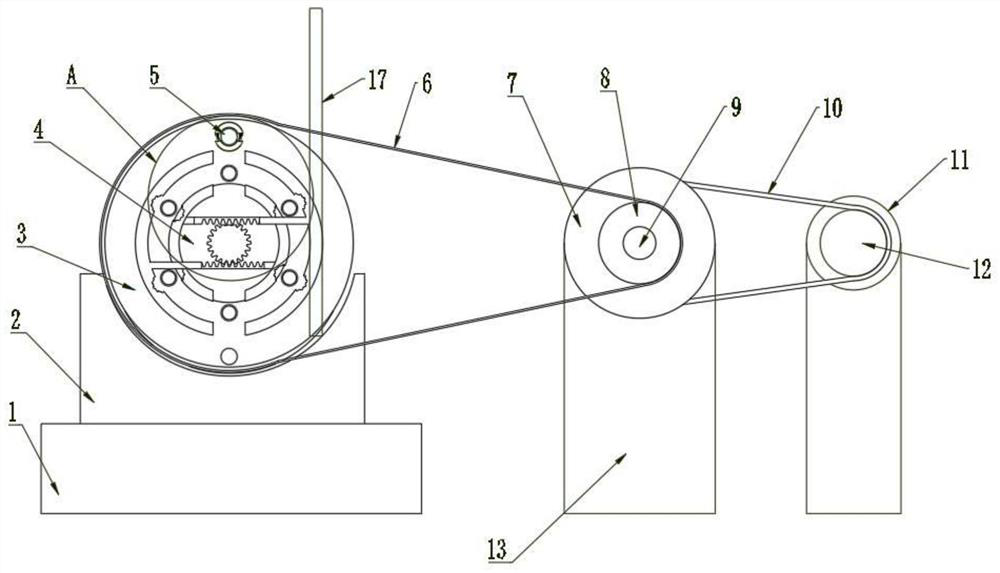
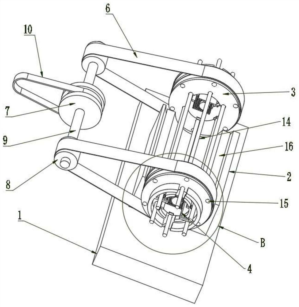
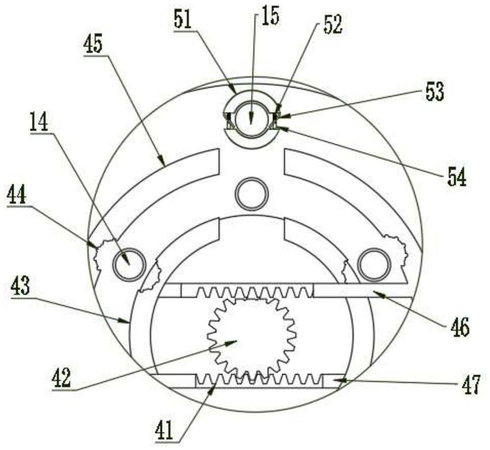
[0023] see Figure 1~4 , in one embodiment of the present invention, a kind of reinforcing bar fixing device for construction industry, comprises base 1, and two rotating columns 3 are installed at intervals on said base 1, and two rotating columns 3 are installed at intervals along the circumferential direction on said rotating columns 3 A plurality of reinforcing bar jacks 15 ...


PUM


Abstract

The invention discloses a steel bar fixing device for the construction industry, and relates to the field of construction industry. The device comprises a base, wherein rotating columns are installedon the base, a first-stage fixing mechanism is further arranged in each rotating column, gears in the first-stage fixing mechanisms are located in installation grooves of the rotating columns and driven by motors installed in the installation grooves, the two sides of each gear are both connected with racks in a meshed mode, one end of each rack is connected with a first fixing plate through a push plate, the other ends extend to outer side of the first fixing plates through pull plates and are connected with second fixing plates, the connecting sections of the two racks and the push plates and the connecting sections of the two racks and the pull plates are oppositely arranged, the first fixing plates and the second fixing plates are located on one sides of the rotating columns, a plurality of anti-skid fixing grooves matched with reinforcing steel bars are formed in the opposite faces of the first fixing plates and the second fixing plates, reinforcing steel bars with different outerdiameters can be pre-fixed, and the problems that at present, the manufacturing effect is not ideal in the process of manufacturing an aperture reinforcing steel bar cage, and the procedure is complex in the process of forming the reinforcing steel bar cage in an enclosing mode are solved.

Description

technical field [0001] The invention relates to the field of construction industry, in particular to a steel bar fixing device for construction industry. Background technique [0002] The aperture reinforcement cage produced in the construction industry is a cage-shaped reinforcement frame formed by using steel bars of the same diameter and binding them together by winding steel bars according to a certain outer diameter requirement; it is commonly used in steel-concrete structures, pouring, reinforced cement piles, etc. The reinforcement cage is the skeleton, which is filled or poured with the corresponding grade of concrete according to the prescribed process, so as to solidify the fluid and improve the strength; but most of the reinforcement cages are manually surrounded by reinforcements in a cage shape when they are initially fixed. End fixing, such a process is more complicated, and some devices that can pre-fix the steel bars cannot be applied to steel bars of differe...

Claims


Application Information

Patent Timeline
Patent Type & Authority Applications(China)
IPC IPC(8): E04G21/12E04G21/18
CPCE04G21/122E04G21/1841
Inventor 蒋俊学
Owner 蒋俊学
Why Eureka
Eureka Blog
Learn More