Ultrasonic system

An ultrasonic system and ultrasonic technology, applied in the field of ultrasonic systems, can solve problems such as unsuitability for continuous use, inability to effectively remove material fragments, complex structure, etc., and achieve the effect of great versatility

Active Publication Date: 2021-01-15
迈克特龙股份公司
View PDF11 Cites 1 Cited by
  • Summary
  • Abstract
  • Description
  • Claims
  • Application Information

AI Technical Summary

Problems solved by technology

[0004] The main disadvantages of known drilling or removal systems are: 1) heat generation on the material the system operates due to heating due to friction with the tool and heating of the (micro) motor; 2) inability to efficiently Removal of fragments of material, which complicates further removal of material in the form of fragments; 3) space available to operators may be spatially limited
This technical solution is complex in its structure and is not suitable for continuous use and replacement of operating elements (inserts) as in dental implants

Method used


Image

  • Ultrasonic system
  • Ultrasonic system
  • Ultrasonic system

Examples


Embodiment Construction

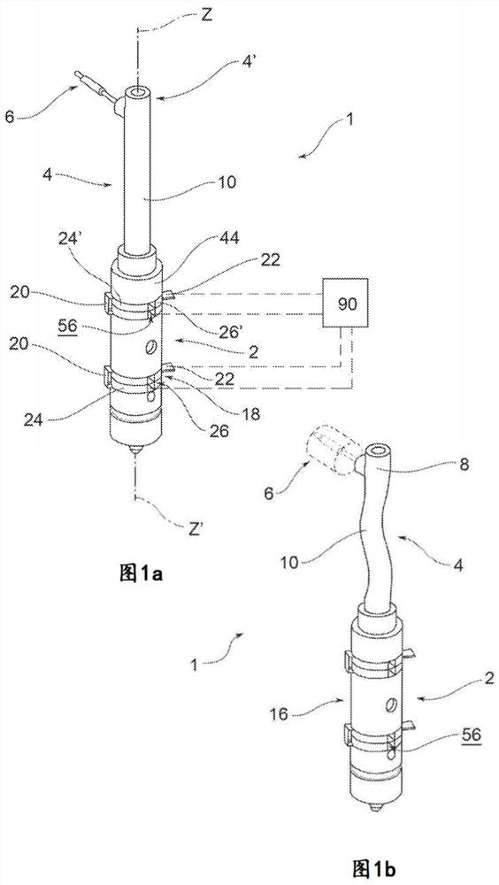
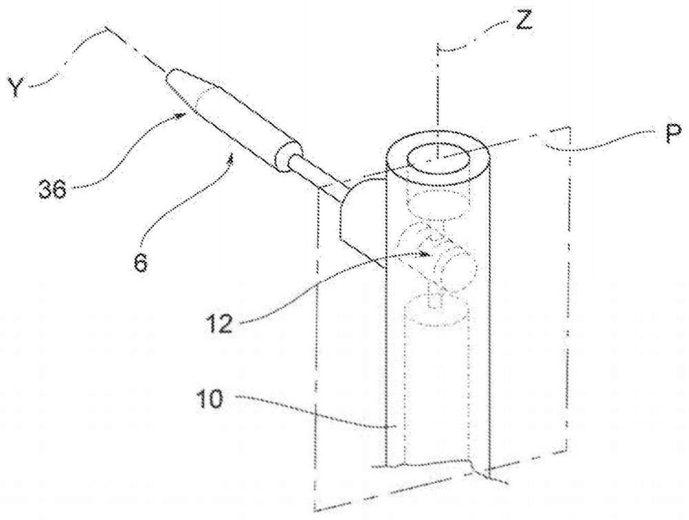
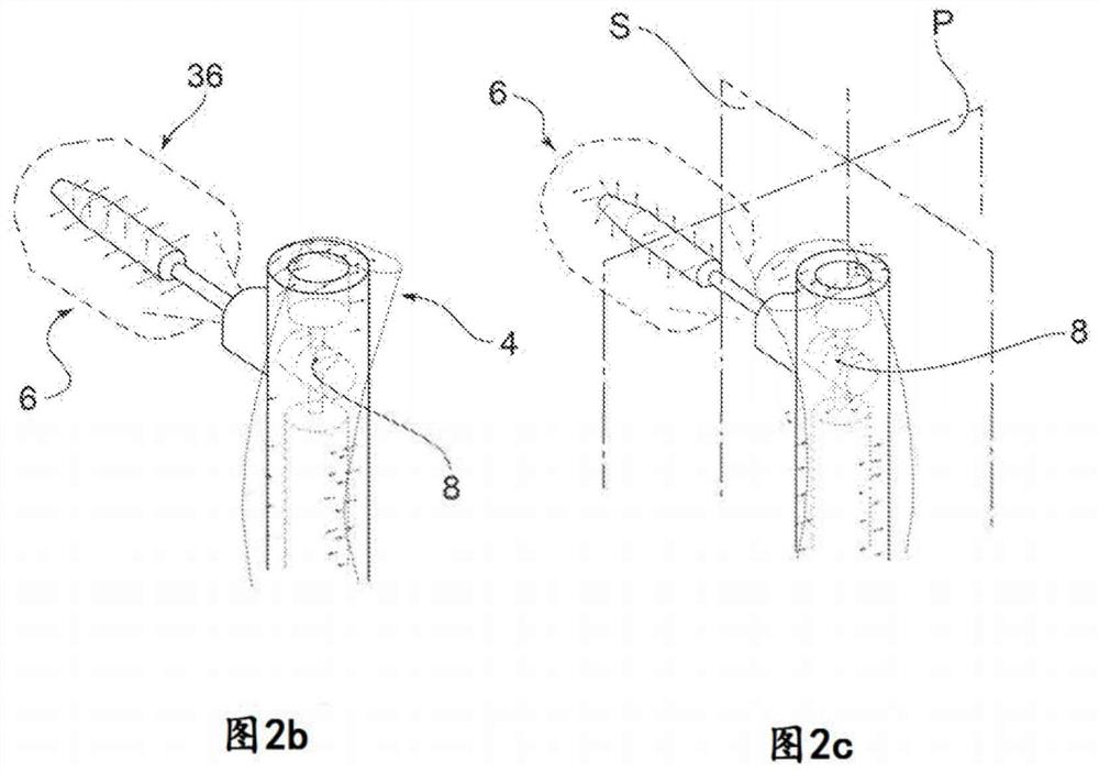
[0056] In the above figures, reference numeral 1 generally designates an ultrasound system 1 comprising an ultrasonic micro-vibration generator device 2 , a waveguide device 4 connected to the generator device 2 and at least one operating element 6 .

[0057] The term "waveguide" refers to a body or part of a body that concentrates and / or amplifies the flexural vibrations of a generator device 2 due to its geometry and position, that is to say also due to its connection to said generator device 2 . part. This component or part of the ultrasound system 1 is also called a "concentrator" because it concentrates (and preferably but not necessarily amplifies) the bending vibrations of the generator device 2, e.g. by reducing its cross-section at least one distal portion thereof. This component or part of the ultrasound system 1 is also referred to as an "ultrasonic horn".

[0058] According to an embodiment, said waveguide 4 is coaxial with said generator device 2 .

[0059] Acc...


PUM


Abstract

Ultrasonic system (1) comprising: generator means (2) for ultrasonic microvibrations; waveguide means (4) connected to and extending away from the generator means (2) so as to bend at least in part; an operating element (6) joined to a stationary bending node (8), so that the flexural microvibrations are transmitted by the waveguide means (4) to the operating element (6) as alternating torsional or flexural microvibrations.

Description

technical field [0001] The present invention relates to an ultrasound system which has a specific and advantageous application in the surgical field, the dental field or in implantology, however, according to other embodiments it can also be used in the industrial or construction field. [0002] More precisely, such a system may be used in areas where removal or drilling of material (eg, but not only of the mineralized type) is required. Background technique [0003] According to the prior art, the formation of the holes or the removal of the material is carried out by means of a tool connected to a shaft which is driven in rotation by a possible micro-motor. [0004] The main disadvantages of known drilling or removal systems are: 1) heat generation on the material the system operates due to heating due to friction with the tool and heating of the (micro) motor; 2) inability to efficiently Removal of fragments of material, which complicates further removal of material in t...

Claims


Application Information

Patent Timeline
Patent Type & Authority Applications(China)
IPC IPC(8): B06B3/00A61B17/00
CPCB06B3/00A61B17/320068A61C1/07A61C8/0089A61C3/03A61B2017/320098A61B17/16A61B17/1622A61B17/1673A61B17/1615
Inventor 尼科洛·塞里索拉安德烈·卡多尼
Owner 迈克特龙股份公司
Why Eureka
Try Eureka